I finished trimming the leg of the angle to the correct lengths. Search for the hardware required and discovered I need to order some phenolic.
Wing Spar
I worked on drilling the second wing spar using the first as a template. This was fairly easy but time consuming. Still, it was easier than all of the layout work that went into the first spar.
Wing Spar
Spent more time today getting the other wing spar blank made to size. I’m now ready to setup and start using the first spar as a template to drill the second spar.
Wing Spar
I spent a fair bit of time today finishing the layout of the wing spar. Once all the layout was complete I setup my drill press and drilled the pilot holes. I still need to put in the large 1-1/2" hole but the rest of the holes are complete. My next stop will be to clamp it to the blank for the other side of the wing and use it as a template to get all of the holes drilled in that spar.
Wing Spar
Working on layout of wing spar.

Right Side Horizontal Stabilizer Tip
I completed the right side trailing tip rib. This consisted of aligning it with the existing holes in the tip rib and drilling new holes in the trailing rib. Next, I installed the tip and layed out the holes between the tip and the trailing rib. I drilled these and colecoed the tip in place.

Made New Tip Ribs for Horizontal Stabilizer
<p>When I started trying to fit the fiberglass tips to the horizontal tail I quickly discovered that they were very hard to fit between the tip ribs and the skin. It seems that there really isn’t any designed in clearance in the plans. After several attempts I decided that the best approach would be to make new tips.</p> <p>Using my cad program I made up a new drawing for the tip rib that allowed for 1/16 of an inch between the skin and the rib. I made up a new forming block and hammered out two new tip ribs. I used the old ribs to locate the 6 holes in each for the spars. Since the new ribs were smaller than the old ribs they would nest with the old ribs and allow me to easily mark the holes for the spare rivets.</p> <p>After completing the new ribs the clearance was visible but the tips were still a snug fit. The next step will be to get the trailing ribs for the fiberglass tips made up and then to complete the fitting of the tips.</p>
Trim Tab Assembly
<p>Today I worked at finishing the trim tab assembly. No real magic here. The plans allow a -3 hinge instead of the -1 so I used up a piece of the hinge that was left over from the rudder.</p>
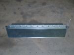
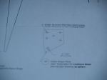
Cable Attach Plate
<p>Today I worked on making the cable attach plate. This part has no dimensions and the plans say that you need to make it from the full size print. I a technique that I use for these types of parts.<p> <ol><li>Start with a piece of drafting paper. It is see through and makes good tracing paper.</li> <li>Place the drafting paper over the print and trace the part. I don’t usually tape the paper down but rather mark a couple of reference points so that I can relocate the paper if necessary.</li> <li>After tracing the part including any hole locations, I use a glue stick to glue the drafting paper to a piece of bristle board. I then cut out the bristle board and I have a cardboard template for the part.</li> <li>I use the template to trace the part onto the aluminum and then use a center punch to mark all of the holes.</li></ol> <p>Now the process is the same as making any other aluminum part.</p>

Trim Tab
<p>I layed out the trim tab on a piece of .032" aluminum base on the dimensions from the planes. Used the Wiss snips to cut out the trim tab and then filled sanded and scotch brited the edges.</p>

You must be logged in to post a comment.