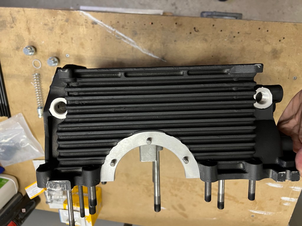
Last weekend, I installed the oil pump. I have a top-mounted oil cooler, so the pump is a straight pump, not the maxi oil pump. The installation manual mentions using form-a-gasket #3 or flange sealant. The Sonex assembly video mentions using Fuellube, available from Aircraft Spruce. I ordered some of this for assembly. The Fuellube is exceptionally sticky. I was worried I might tear the gaskets when applying it. Again, this was a relatively simple assembly effort.
One thing that I struggled with was finding the correct bolts. The manual does not mention the bolt part numbers. The bolts are the same thread size as the intake manifold bolts, and I double-checked the length to be sure they would not bottom out before completing the assembly. It seems there were two sets of these bolts in the kit. I will follow up on these bolts before I finish the engine.
Last weekend, I installed the oil screen and oil sump. This was pretty simple. I had ordered a sump cover with dual ports. One thing I noticed, consistent with the assembly video, is that the nuts do not engage far enough into the studs for the nylon to catch. The assembly manual mentions the use of either acorn nuts or the nyloc nuts. I think the assembly would be better with the acron nuts but I did not see any in the kit.
I have been working on the rocker shaft installation for a week or two now. Based on everything I’ve learned, I suggest following the AeroVee manual. It just works.
Being a mechanical engineer, I put too much thought into this process and concluded that what is presented in the manual is correct, even if it seems very simplified. When I started, I wondered about the placement of the swivel pad on the valve stem. My initial thought was that due to the angular or rotational motion of the rocker arms, the pad would slide back and forth on the top of the valve stem. While this is correct, I also thought that they should slide back and forth across the centre of the valve stem in an ideal setup. This part I am not so sure about.
I read a lot of forum posts about VW type 1 engine valve geometry, and many talk about the setup at 1/2 lift. The idea is that you want the correct geometry at 1/2 valve actuation. What I mean by correct geometry is that you are looking to have the line from the centre of the rocker shaft to the point of contact (or point of no moment, more on this later) being perpendicular to the valve stem. This made sense to me as you will apply some side loads to the valve stem on either side of this position as the rocker arm moves through an arc.
To change the geometry, you can either make changes at the adjuster or you can shim the rocker arm shaft. The AeroVee manual and many websites suggest setting the adjuster to between 1 and 2 turns out from the swivel pad being against the rocker. (The AreoVee manual says 1-1/2) turns. With this setup, you can only add or remove shims under the rocker shaft to change the geometry.
The mounting studs for the rocker shaft are not parallel to the valve stems. This means that as you add shims under the rocker shaft, you are both moving it upwards in the direction of the end of the valve stem and, at the same time, moving it closer to the valve stem. This changes the angle of contact at 1/2 lift and the position of contact on the end of the valve stem. Adding shims generally moves the position of contact away from the rocker shaft while removing shims does the opposite.
The AeroVee manual wants the rocker shaft shimmed so that the point of contact is not in the centre of the valve stem but past the centre of the valve stem away from the centre of the rocker shaft when the valve is fully closed. This did not make sense to me because as the rocker arm rotates, it will move further away from the rocker shaft until it reaches a point where the radius is 90 degrees to the rocker shaft and then the position of contact will move back towards the rocker shaft for the remainder of its movement. I thought it would make sense to have the starting point closer to the rocker shaft, then as the rocker arm rotates, the position of contact would move through the centre of the valve to a point on the opposite side of the centre at 1/2 lift and then would return back to its starting point at full lift.
Another consideration is trying to get the maximum lift of the valves available from the cam. Depending on the geometry at both the push rod end of the rocker and the valve end of the rocker, you will get different amounts of lift. I’m unsure what the actual lift for the AeroVee should be, as I didn’t check out the cam information when I unpacked it.
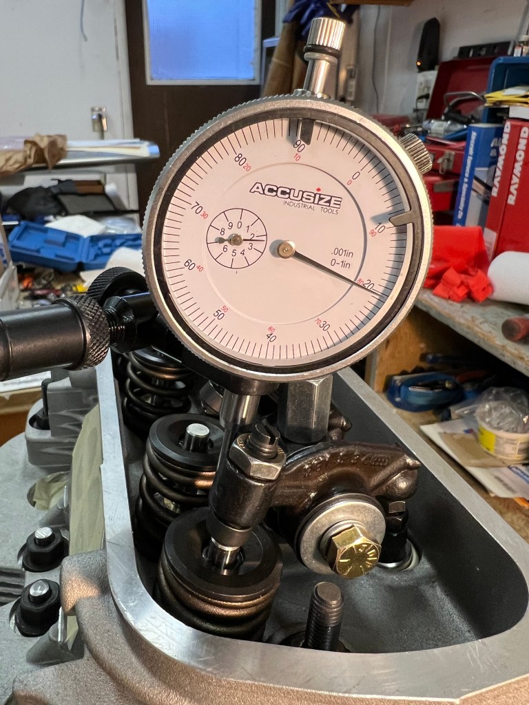
I purchased a dial indicator and mount during this exercise to find the 1/2 lift point and examine the geometry. During my various measurements, I got a maximum valve lift of 0.440″ measure at the top of the valve.
The Dial Indicator was Zeroed at Full Valve Activation
While reading the various forum posts, I came across one suggesting that the point of contact between the rock and valve with a swivel pad adjuster is actually the centre of the adjuster ball. This actually makes sense as the point of contact is where no moment is transmitted, and this will occur at the center of the ball.
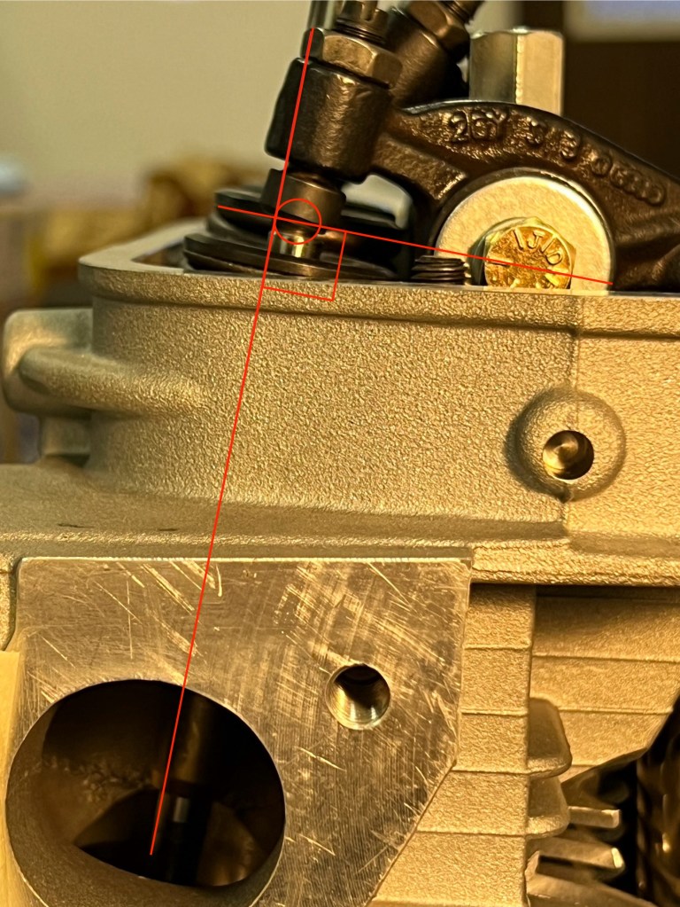
With all of this in mind, I experimented with different numbers of shims under the rocker shaft. What I found was that with one 0.030″ shim, I was able to get the most valve lift and, at the same time, very close to the magic 90 degrees between the line from the rocker arm pivot to the center of the swivel ball and, the valve stem at 1/2 lift.
I noticed that the swivel pad’s movement across the tip of the valve is very small. I also found that with one shim in place, the position of contact was just past the centre of the valve, away from the rocker shaft, as described in the AeroVee Manual. At this point, I decided that the manual was right and that it would have been better just to follow it as the setup described. With all the work I did measuring thing I was not able to get any better setup.
Half Lift – One Shim InstalledExhaust Valve at Half Lift
With all of this figured out, it’s now time to get back to the rocker shaft installation and the trimming of the pushrods.
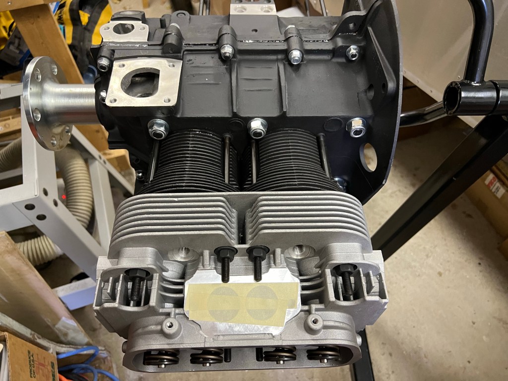
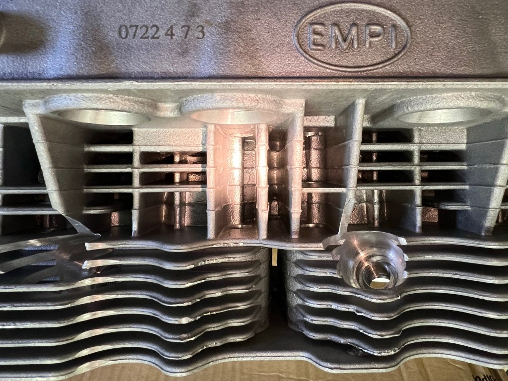
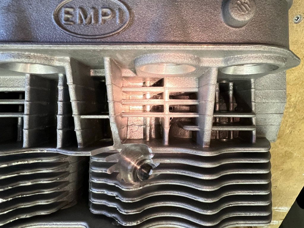
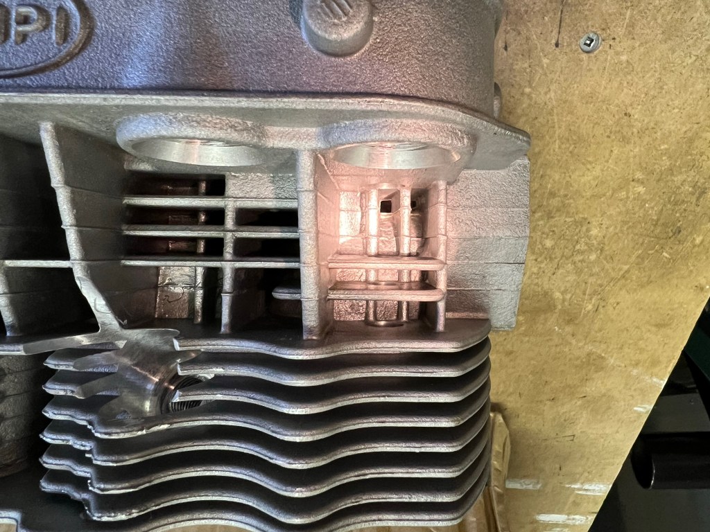
I worked on installing the cylinders, pistons and cylinder heads on one side of the engine today. My goal was to complete one side before starting the other. The reason for working on one side at a time was to try and ensure a good seal for the cylinders. I figured that if the cylinders were installed, but the cylinder heads were not, there would be no pressure to help seal the cylinders and allow the Permatex Aviation Form-A-Gasket #3 to seal properly. I’m not sure if this is entirely true. It claims to be non-hardening and slow-drying.
I started by reviewing the cylinder spacer selection based on wanting to run 8.0: 1 compression for aviation fuel. I used some mineral spirits to clean up excess oil from the mating surface of the cylinders and the spacers. Next, I checked the piston orientation in each of the two cylinders I was going to start with to be sure the arrows would be pointing to the flywheel. I pulled the pistons out the bottom of the cylinders enough to allow the wrist pins to slide out. I put the snap rings in one side of each piston so that I could install the pistons and still be able to put the snap rings in from the front and back of the pistons after sliding the wrist pins in.
Orienting the wrist pins required some though. For the first piston, it does not matter which direction the wrist pin slides in from. But when you install the second piston you have have the wrist pin slide in from the outside, away from the first cylinder.
After installing the cylinders and spacers, I installed the cylinder head with the head gaskets and push rod tubes. Next, I measured and started trimming the cylinder studs. I needed to cut down 5 of these to ensure clearance from the rockers and the intake manifold. For each of these, I used some form a gasket on the threads to the crank case as I reinstalled the studs. I plan to do the same for the remaining studs after re-installing the studs that I cut down
I started today by getting out the cylinders heads. I want to have them ready to install right after I install the cylinders. Why? The cylinders are installed using Permatex Aviation Form-A-Gasket #3 and I would like to install the cylinder heads and have them secured while the Permatex cures. Since I only work on the engine in frequently I did not want to install the cylinders and then leave them to sit for a few days or weeks until I got to the cylinder heads.
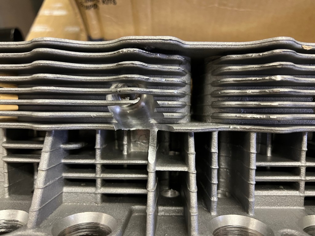
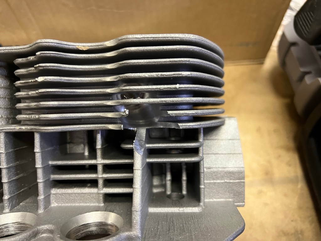
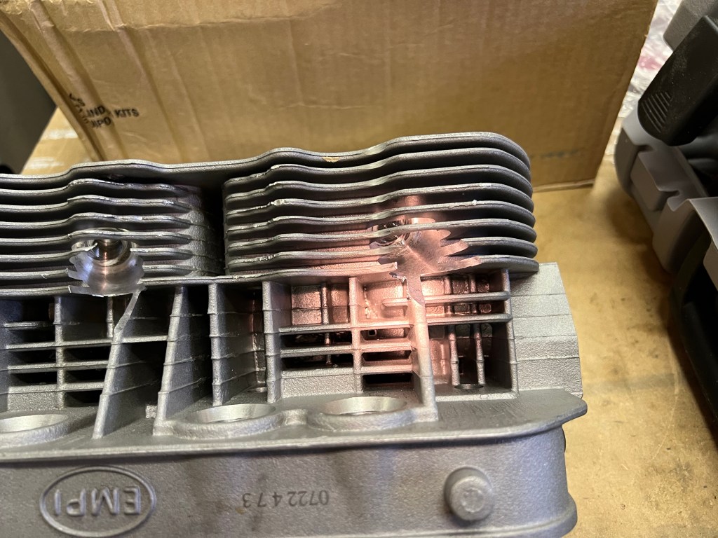
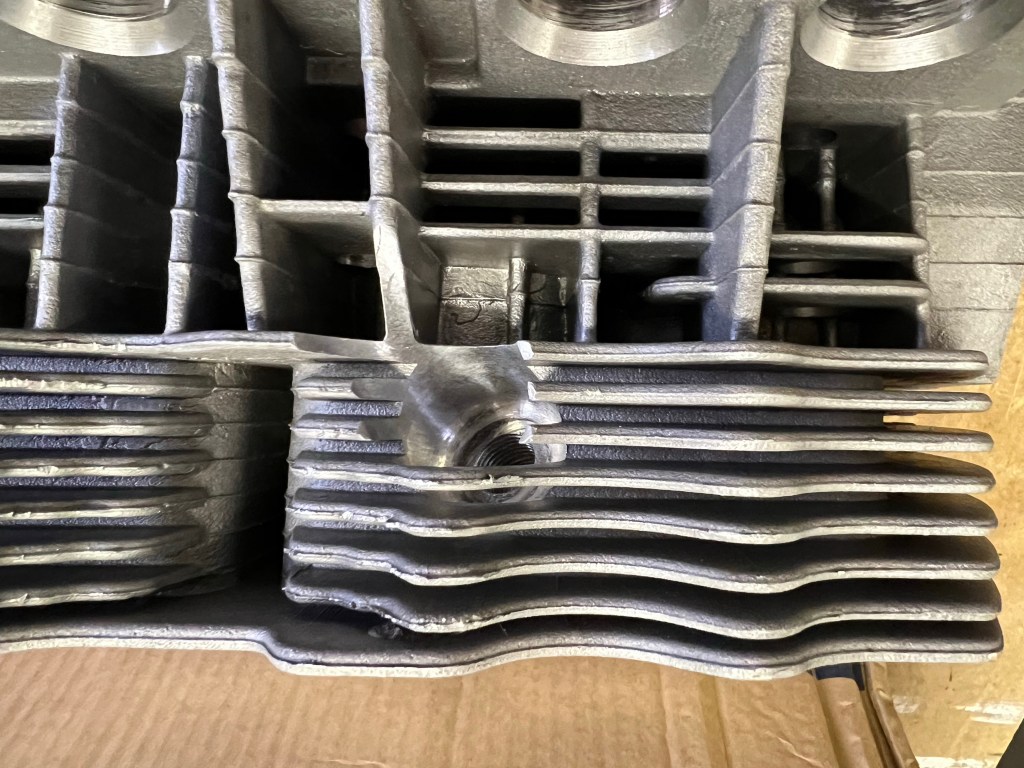
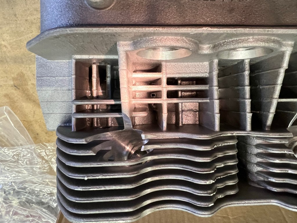
The instruction to clean the heads of machining debris is shown in bold text and identified as Important right after the parts required list. Hopefully, nobody skips ahead to the first step without doing the required cleaning. I found alot of debris in my heads.
Some of the Debris found in my Cylinder Heads
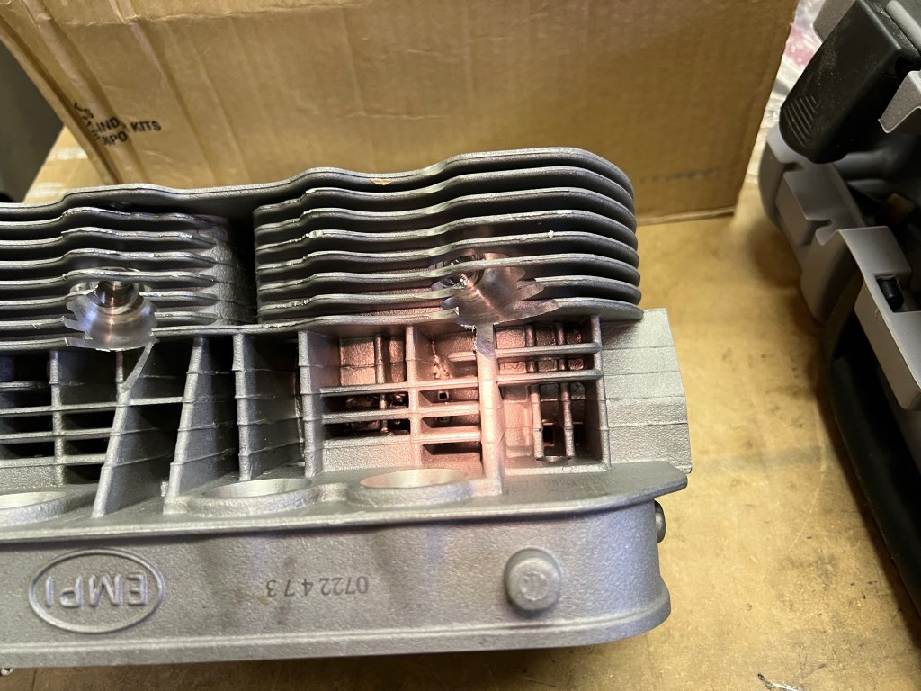
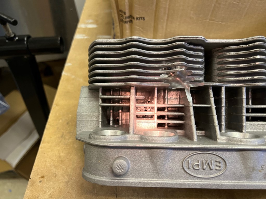
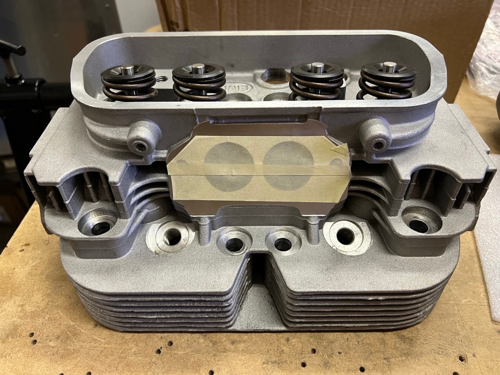
Before I started working on the chips I used masking tape to close up the intake and exhaust ports. I still planned to blow these out later but I figured it was better to keep the chips out of there right from the start.
Ports Taped Closed
I used a small scrapper and a deburring tool to remove the worst of the aluminum chips. I also used a piece of bare 14 gauge copper wire to get to the bottom of some of the tight areas to get the chips out. In the areas where the secondary spark plug holes were added, I cleaned up the sharp areas with a Dremel tool and then some scotch bright pads to break the sharp edges. I used compressed air on several occasions to blow out the chips.
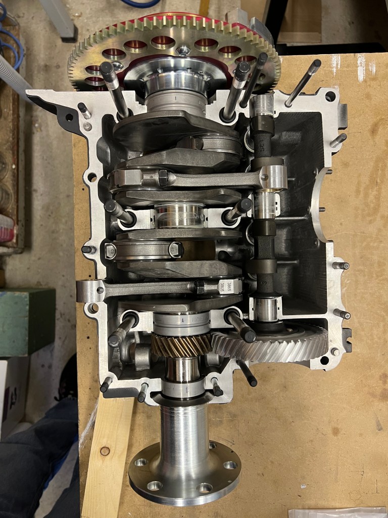
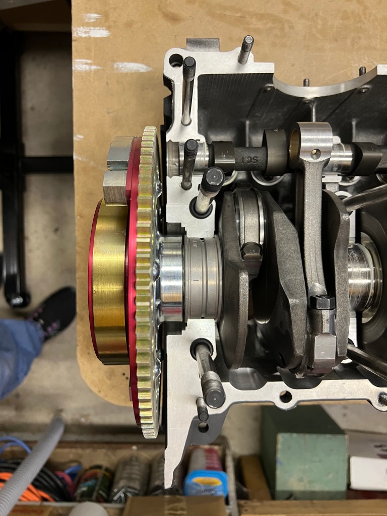
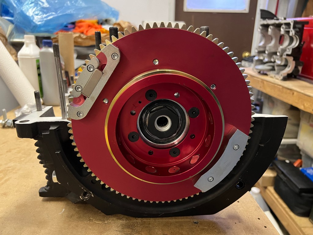
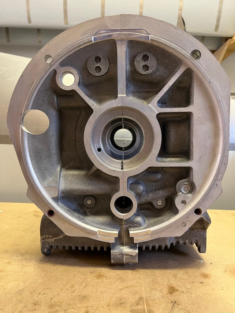
I continued working on assembling the crankcase today. Previously, I installed the crankshaft and camshaft. Today, I finished fitting the flywheel. This took a bit of polishing of the dowel pin holes as I could not get the flywheel to fit onto the end of the crankshaft.
Once the flywheel was installed, I used my impact gun to tighten the 36 mm bolt. Next, I measured the crankshaft end play and recorded the measurement in my installation manual. It measured 0.061″. This means that I need a shim thickness stack of 0.055″ to 0.058″ to provide the required 0.003″ to 0.006″ end play.
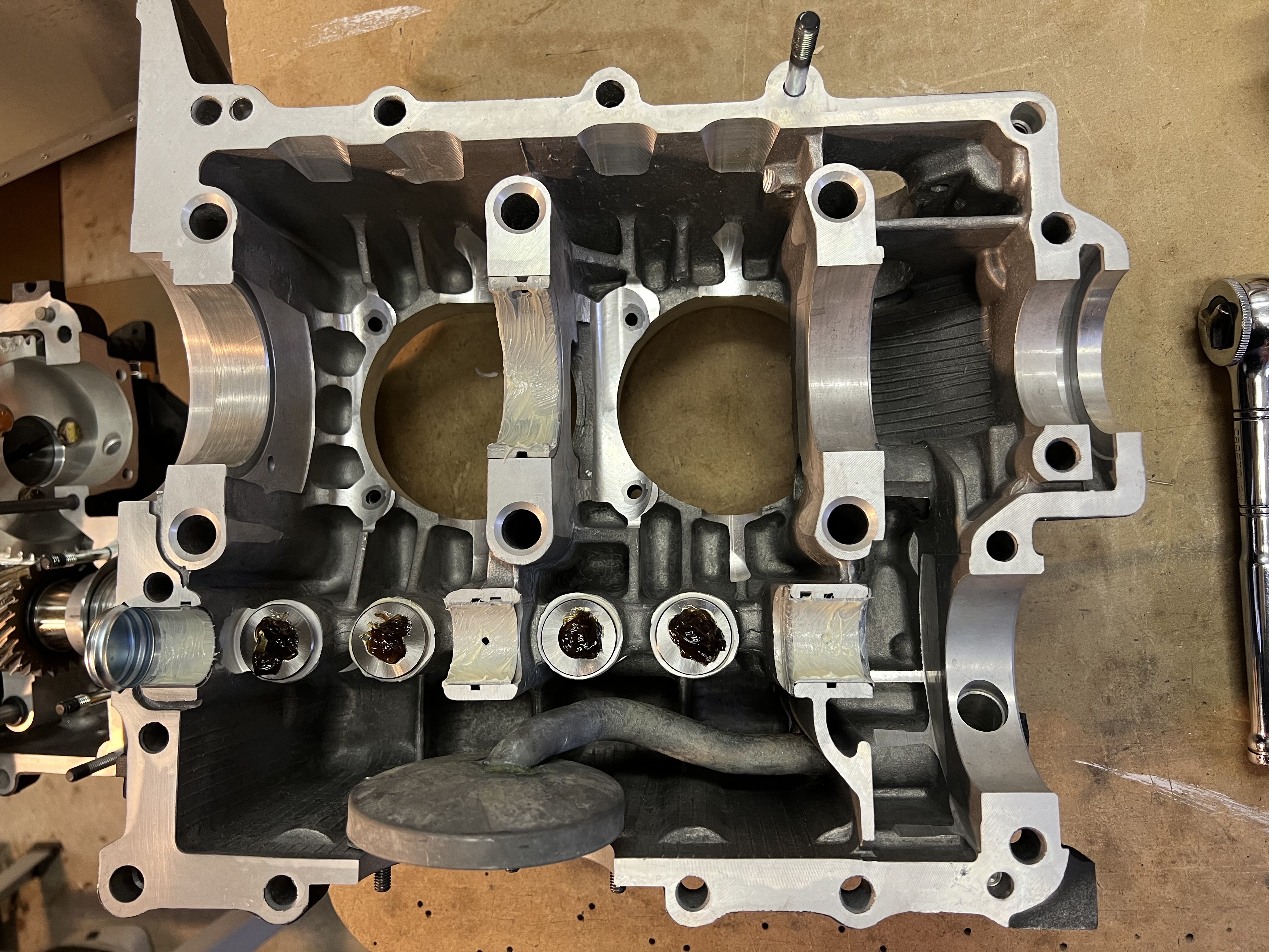
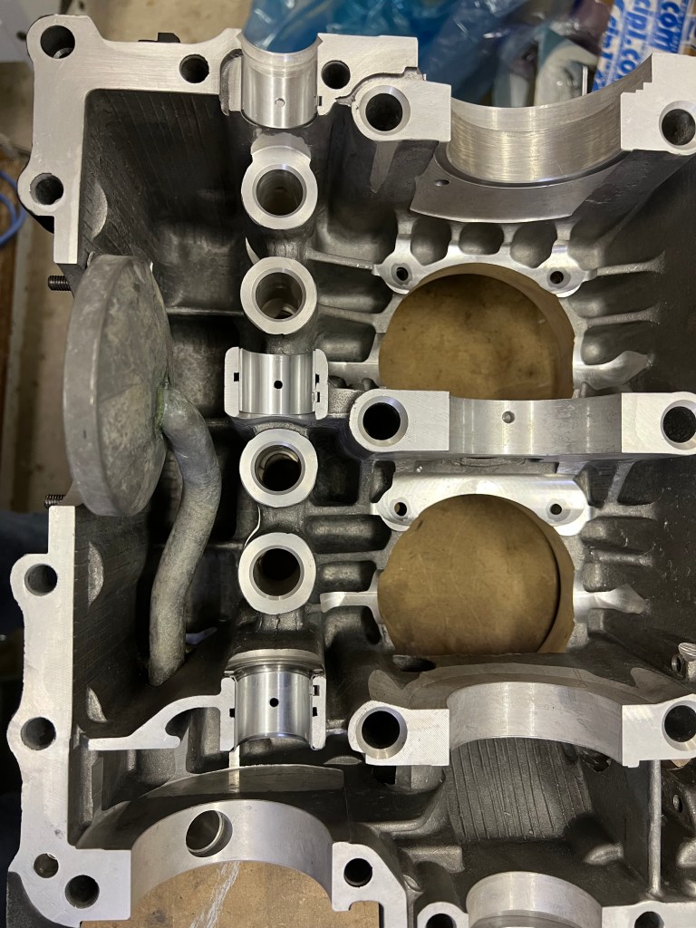
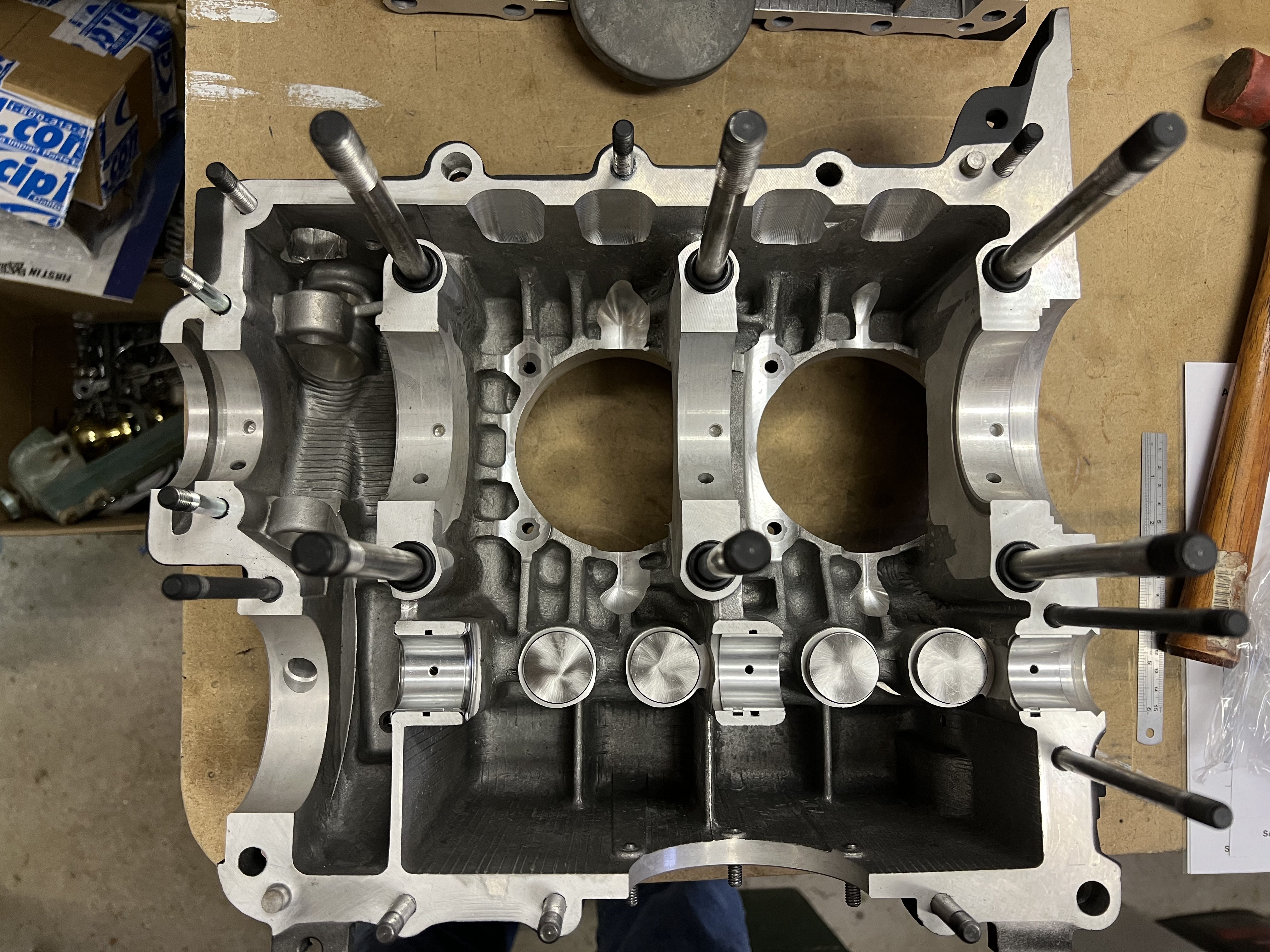
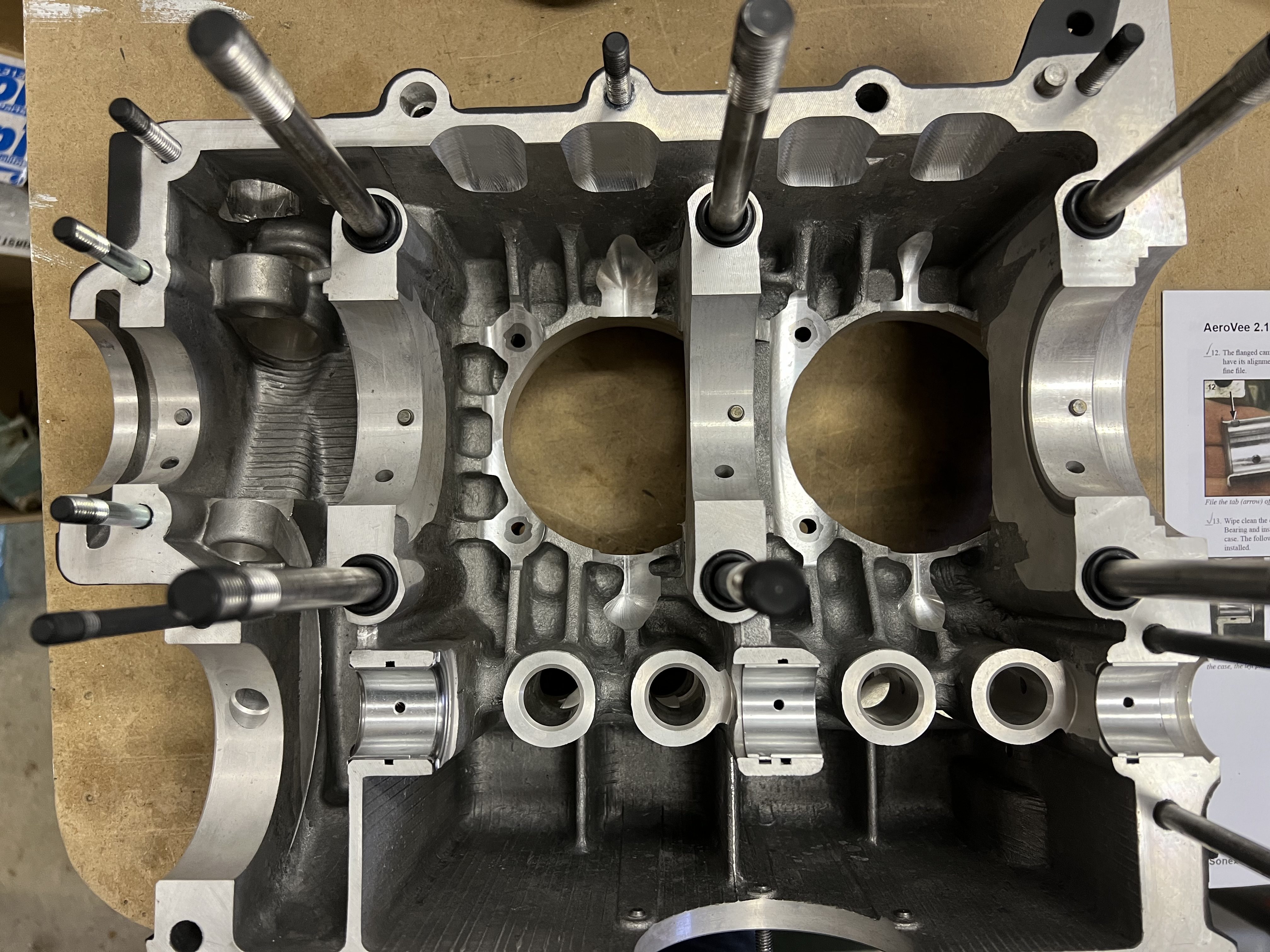
Once the end play was determined, I found the fasteners and cam plug I needed to assemble the two crankcase halves. I installed the lifters and applied the grease to them. I lubricated the bearing halves for the camshaft and crankshaft. Next, I applied the Permatex Aviation Form-A-Gasket #3 to the case half that does not have the studs.
Crank Case Prior to Applying Permatex
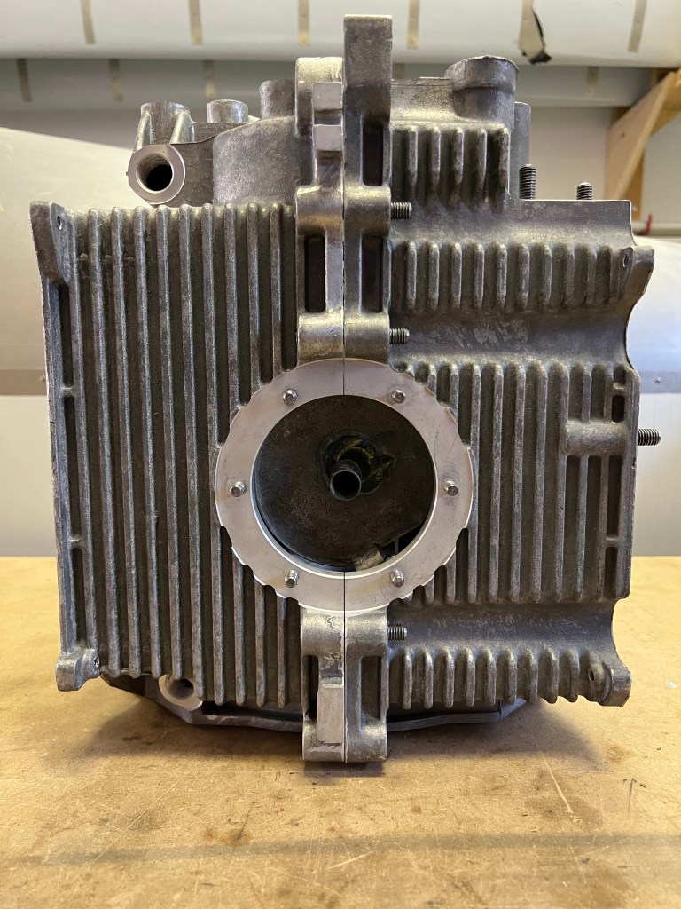
After applying the Permatex, I assembled the case halves and followed up with the torquing sequence for all the fasteners. The manual mentions 10 studs for the AVC-Z01-23 stop nut. I had a hard time finding all 10, but in the end, one faces the opposite way and needs a bunch of washers to allow the nut to tighten up on the stud.
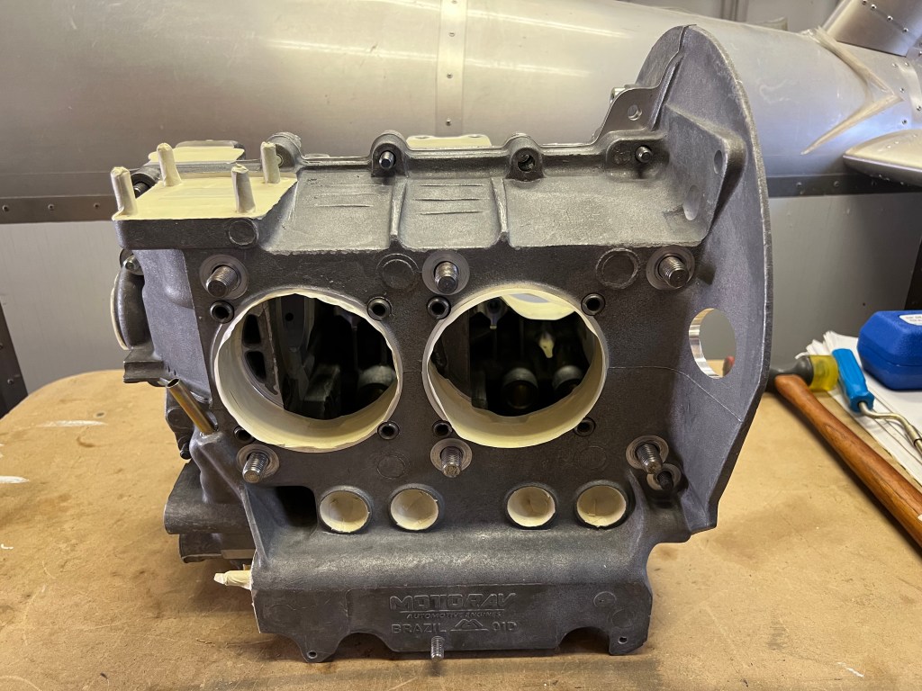
I started the crank case preparation shortly after receiving the engine kit back in August. I inspected the interior of the case for any remaining machining chips. I blew the case out with compressed air and spent time using a deburring tool to clean up any edges or holes that appeared to have burrs. I also looked at the cast in drain passages at each end of the for both the crank and the cam shaft to be sure they were clear to allow oil to return. After this, I washed the case in soap and water, blew it dry and set it in the sun for a final drying.
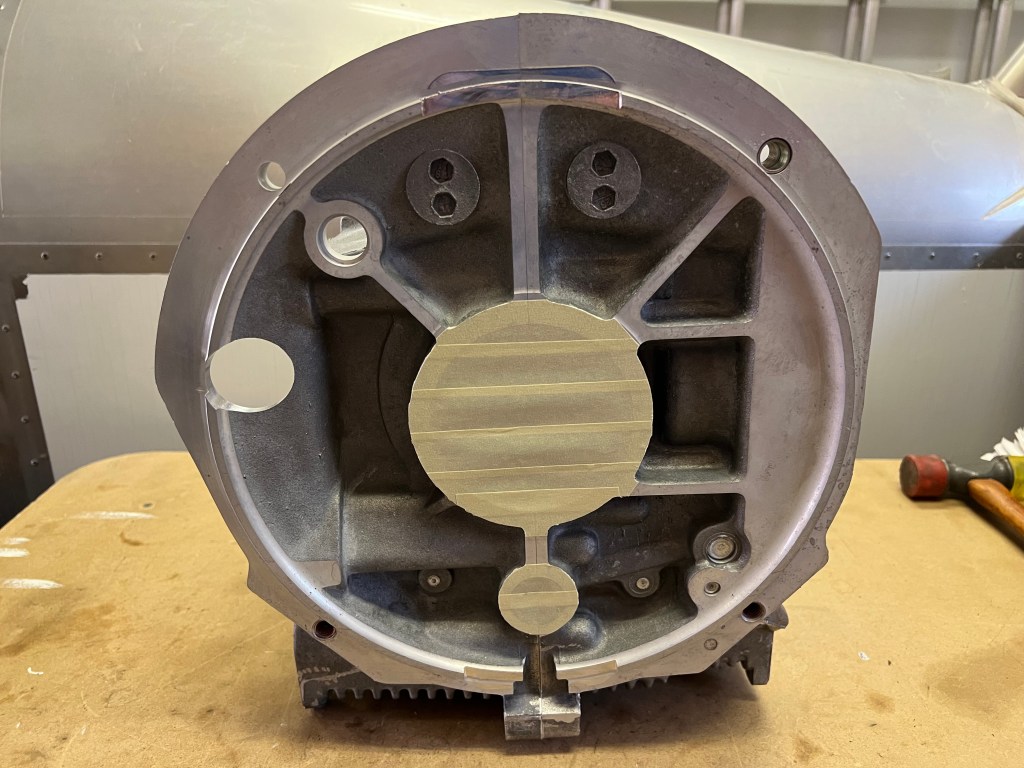
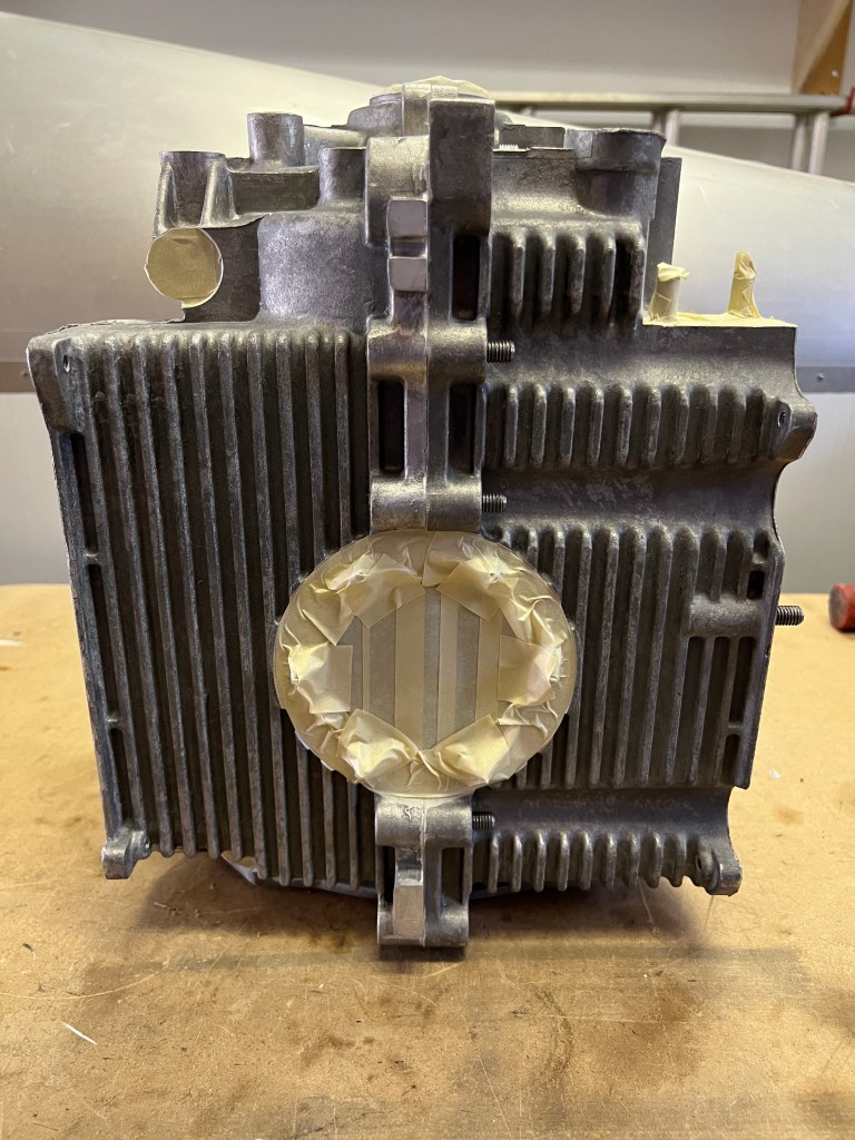
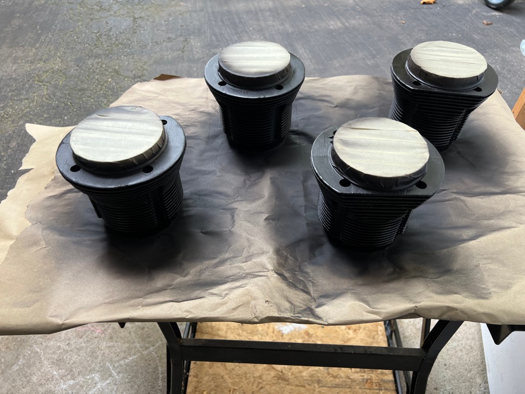
Next, I mated the two case halves and proceeded to mask up all of the openings so that I could paint the outside of the case. I also decided to paint the cylinders at the same time.
I decided to leave the installation of the head studs until after the case was joined or at least until I had an engine stand to put the case on. This seemed to make it easier to prepare the case for assembly as the two halves would lay on the work bench easier without the studs.
The next step was to install the oil pressure relief valve and the oil control valve. These were lubricated with oil and installed according to the manual. There is no torque spec for the plugs. The original VW plugs have slotted heads are are not intended to be tightened more than is required to compress the gasket. The plugs in the kit have a 17mm head. I used a 17mm wrench and made sure that the plugs were tight but only used moderate pressure to ensure I didn’t over tighten them in the case.
I installed the main bearing stud seals and proceeded to work on the cam bearings. I wiped the cam journals and installed the bearings in the left half of the case. I inadvertently installed the wrong bearing in the front (prop) end of the engine. This was noticeable because the longer bearing covers most of the oil return passage. Once I noticed this I swapped the two bearings. For the right half of the case, the flanged bearing must have its anti-rotation tab filed off. I filled this off with a small flat file and fit the cam bearings to the right hand side.
The final steps in the preparation were to test fit the lifters to be sure they didn’t bind and to verify the cam did not interfere with the lifters. Then the dowel pins were installed in the various main journals to anchor the main bearings and the two half journal bearings were installed. Fitting the dowel pins was a bit of a challenge. If you don’t get them started just right they will not go in. It took me a bit to get two of them to fit correctly.
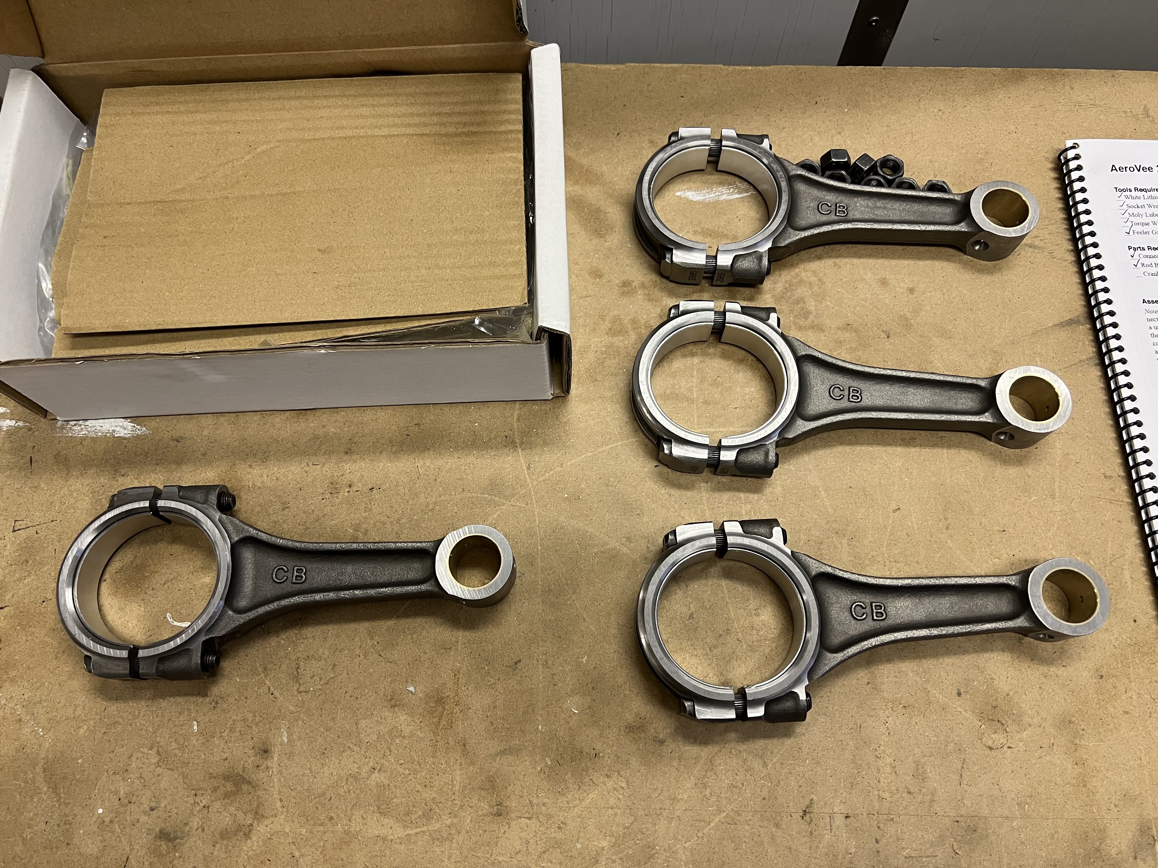
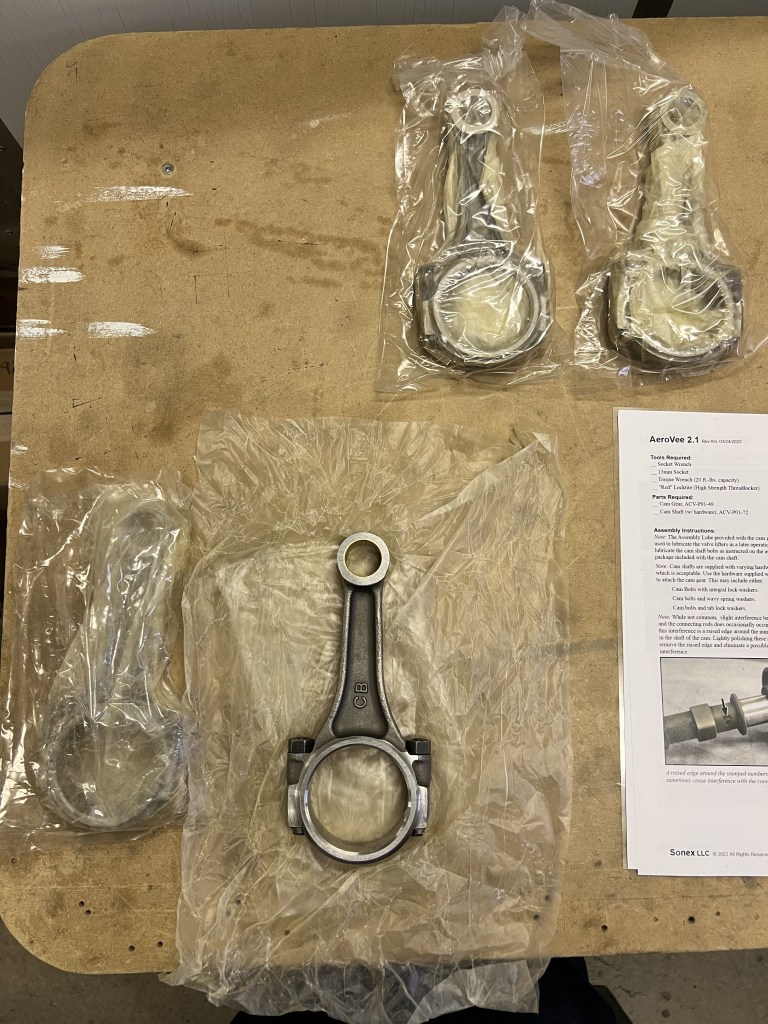
I continued working on the connecting rod assembly. After loosening all of the fasteners I cleaned the mating surfaces and installed the bearings.
Connecting Rods with Bearings Installed
Next, I decided I wanted to check at least one of the journals for clearance. I purchased some plastigage online and proceeded to assemble the first rod on the crank with a piece of plastigage to check the clearance. The clearance is expected to be between .002″ and .0025″.
Rod Assembled to CrankPlastigage on Crank JournalPlastigage on BearingClearance – Just under .002″Clearance – Just under .002″
When I disassembled the rod from the crank the plastigage showed just under .002″ and more than .015″. This seemed appropriate and I did not check the remainder of the clearances as all of the parts are new.
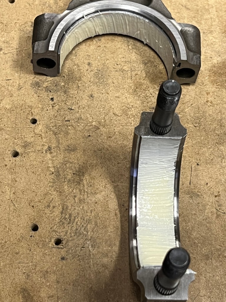
I applied white lithium grease to all of the bearings and assembled the rods to the crank. I followed the directions in the assembly manual to keep all of the anti-rotation notches at the bottom of the crank. This resulted in the matching numbers also being towards the bottom of the crank. I did some research online and found that having the anti-rotation notches to the bottom is what is expected when assembly a VW type 1 engine.
Grease applied to the bearings
I assembled all of the connecting rods to the crank and torqued the nuts in four steps to the required 29 ft-lbs. I then put the crank and rod assembly back into an extra large freezer bag with some desiccant to absorb moister and put it away for future assembly.
Today I did a little bit of prep work for the crank assembly. I located all of the connecting rods, the rod bearings and the crank shaft.
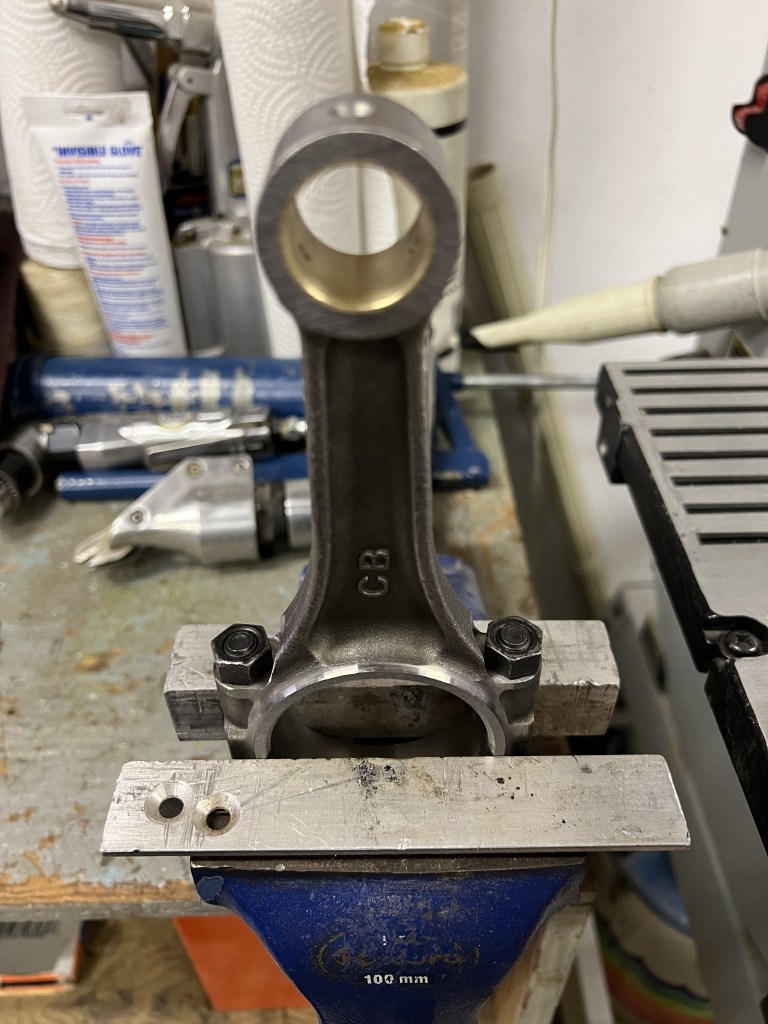
I opened up the connecting rods and loosened the bolts.
The nuts were quite tight, so I needed to clamp the connecting rod in the vice between two aluminum angles (to prevent damage). I was then able to get enough force onto my 14mm socket and ratchet to loosen each of the nuts. I left the nuts finger tight and rewrapped the connecting rods for storage.
The next step is to clean the mating joint between the rod and the rod cap, install the bearings and then install the rods onto the crank. I stopped before doing this to check the bearing clearance using plastigauge. The parts are new, so I expect the bearing clearance to be correct, but checking it will allow me to verify this and not assume anything. Unfortunately, I don’t have any plastigauge, but I have ordered some. I’ll continue the assembly after the plastigauge arrives.
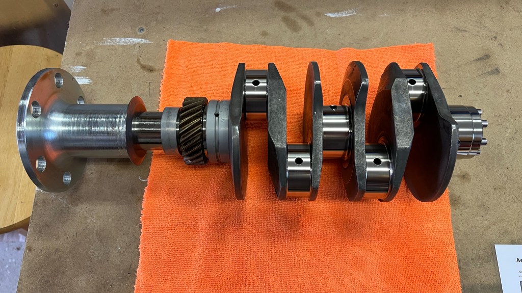
The title is a bit of a misnomer. I didn’t need to assemble the prop hub as I ordered the crankshaft with the prop hub installed. But I did complete the rest of the crank shaft assembly.
AeroVee Crankshaft
I used mineral spirits, as directed in the assembly manual, to clean the crank and I used pipe cleaners to clean the oil passages. I did not clean up the journals at the prop end as bearings had already been installed by Sonex. I was also careful not get get mineral spirits in the front oil passage that runs from the the number two cylinder connecting rod journal to the number three main journal.
I removed the hex plugs in the crankshaft at the end of the four oil passages that connect the #1, #2 and #3 main journals with the four connecting rod journals. Once all the cleaning was complete I installed the 4 hex pugs with blue locktite as directed in the assembly manual.
The final step was to torque the prop hub bolt to 80 ft-lbs. Applying the torque was a bit of a challenge, and I had to strap the crankshaft down to the bench since I did not have anyone to hold it.


You must be logged in to post a comment.