The drive horn shown in the plans has no dimensions but is drawn full scale. I decided that the quickest way to make this part was to start with a template. I used a piece of drafting paper to trace the drive horn from the plans. I then glued the drafting paper to a piece of bristol board and cut it out. This provided a rigid template that I could trace for the final shape on the aluminum.<br /><br /> I traced the shape onto the aluminum and used the band saw to cut out the rough shape. Next, I started the sanding.
Holes In The Attach Plates
I started work on the large oval hole and the tail relief. On one of the attach plates I decided to drill a series of 3/32 inch holes around the perimeter of the large oval hole. Next, I used a coping (sp?) saw to cut between each of the holes and get a rough opening. Finally, I used a sanding drum in the drill press to start cleaning up the oval. I also used the band saw to cut the tail relief.
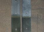
More Attach Plate Work
I finished sanding the large oval hole. Next I setup a fence on my drill press to allow me to drill all of the 3/32 inch pilot hole in a straight line. I clamped a piece of hardwood to the drill press table 1/4 of an inch from the centerline of the drill bit. This lets me drill exactly 1/4 inch from the edge of the part. All I have to do is line up each of the marks measured from the end of the attache plate.
Idler Plate
I drilled 3 pilot holes in the idler plate. All are 3/32" dia. I’m not exactly sure what size to drill the final holes. Two of the holes are called out at 1/4" and one is for an AN3 bolt. I haven’t figured out what goes in the 1/4" holes and I have found conflicting information on the AN3 bolt. Some literature says to drill it 3/16" and some info says I should drill it smaller so that I have a tighter fit on the bolt. I left the part with the pilot holes and will open them up later.
Spacer Block
I made the small spacer block. It was fairly straight forward. I used the bandsaw to cut the material and then files, sandpaper and scotch brite to finish it.
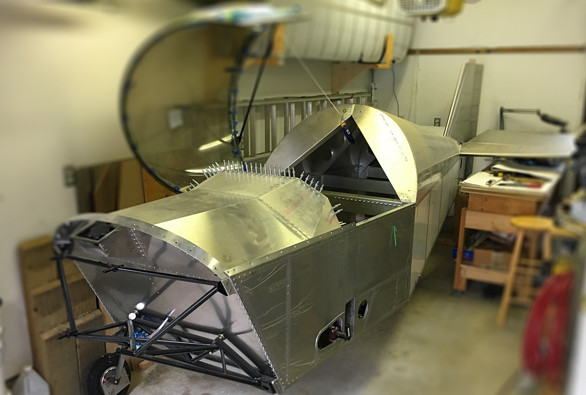
Left Hand and Right Hand Attach Plates
I started with one of my previously created strips of aluminum that is almost the correct width. I cleaned up the long edges using the vixen file, mill file, sandpaper and scotchbrite. The brought the strip to the correct width. Next I started laying out the part using an ultrafine sharpie right on the aluminum. I had to measure one of the angles at the nose of the part as it was not dimensioned on the prints.
More Work Today On the Attach Plates
Well, I got back at things again today. I find that an hour at a time is about right and gives me some thinking time. I finished marking out the attach plates and then cut them out on the band saw. I keep remembering to use a candle on the blade before any serious cutting and it sure keeps the blade clean. I used the bench sander after cutting to start cleaning up the edges.

Left and Right Hand Lower Horizontal Splice Plate
I formed the bend on these two parts. I noticed that the hardwood dowels I have been using were being crushed with use so I switched the one on the inside of the bend for a 1" OD socket. This seemed to work well. As usual I ended up with a bit of orange peel on the surface that disappeared with an application of scotch brite. I had a hard time guessing at the spring back and ended up over forming the parts a little. A few taps with a rubber mallet brought the bend back to the correct angle.
Left and Right Hand Upper Vertical Splice Plates
I formed these parts as well. I started by marking the tangent lines and then formed them the same as the others.
Idler Plate
With all of the splice plates completed I started on the idler plate. It was fairly simple to cut out and create the radii on the ends. I have it marked for drilling but I need to determine the diameter for the last hole. It takes a fastener but the diameter is not marked. I’ll have to lookup the correct size and decide if I want to ream the hole or just drill to size. I think reaming would be a good idea as it will ensure a tight fit for the hardware. I don’t want any slope in the control system.

You must be logged in to post a comment.