Painting the Cylinders

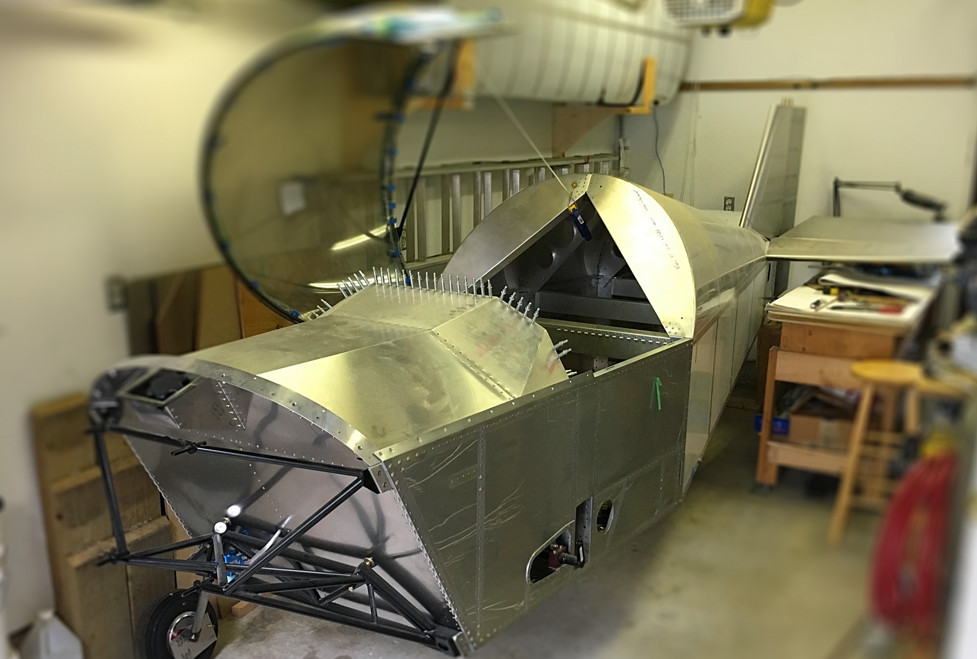
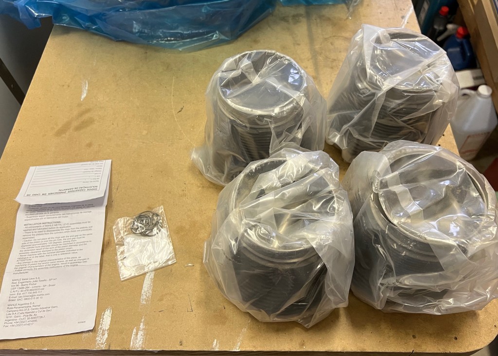
Today I painted the cylinders for my Aerovee. When I first received the engine kit I noticed that one box seemed to be a bit damaged on the corners. I took photos but upon further inspection found that the box contained my cylinders and they were fine. Since the cylinders were round the corner damage to the box did not affect the cylinders.

Cylinder Kit inside of Shipping Box
Cylinders Inside Box

After opening the box I found the retainers for the piston pins in a bag as well as some assembly instructions in addition to the cylinders and the pistons inside them.

Cylinder Box Contents

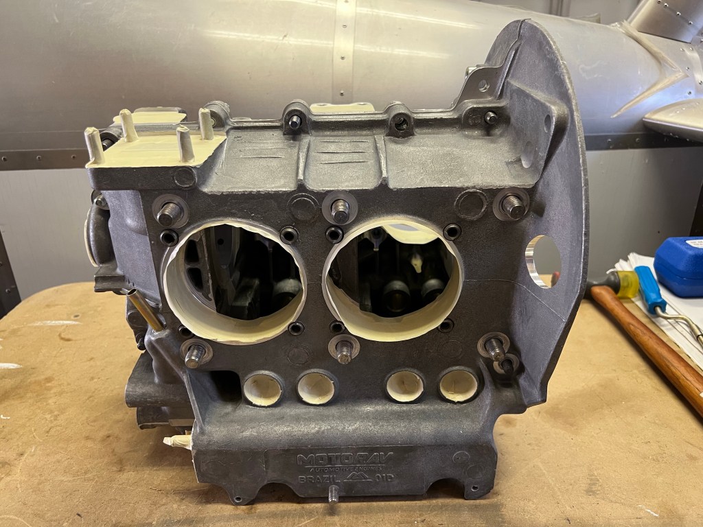
Next I proceeded to mask the cylinders with the pistons inside as shown in the AeroConversions assembly video. After getting the cylinders prepared I realized I would need different paint for these compared to the engine case. For the case, I just used a flat black enamel. The case should not exceed 400F. I had read in Bob Hoover’s blog (https://bobhooversblog.blogspot.com/2006/11/vw-case-paint.html) (https://bobhooversblog.blogspot.com/2006/11/vw-case-paint.html) that the cas should be fine painted in an oil based enamel.

Cylinders Prepared for Painting

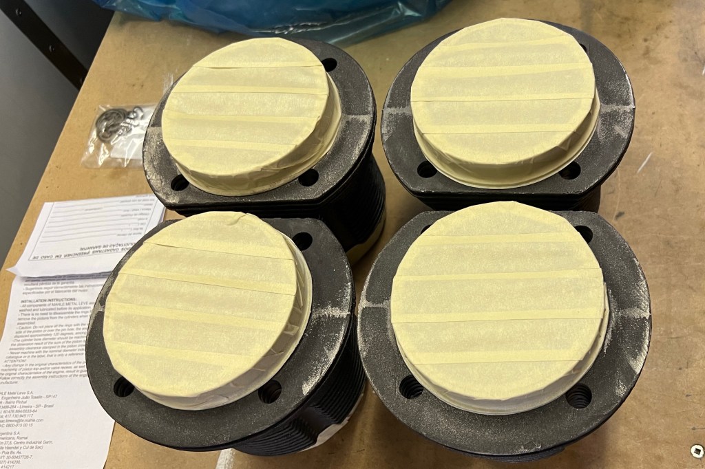
I felt that, for the cylinders, a higher temperature paint would be more appropriate. BBQ flat black seems to be a common paint used and was recommended in the AeroConversions video. I bought a can of this for the cylinders.

Painted Cylinders

Preparing Engine Block For Paint

I continued preparing the engine block for paint today. I deburred a couple of remaining threaded holes and applied masking tape to the various surfaces that need to be kept free of paint. The Aeroconversion AeroVee assembly video helped me identify which of the various surfaces needed to be protected. For the cylinder openings in the block I used the lids from various coffee cans to close in the openings.

Front View (AeroVee) with most openings taped up.
Side view with cylinders still open.

After getting the engine fully masked I put it on a bench outside and proceeded to apply the paint. I let it dry and then a few days later removed the masking.

Instrumentation Re-Boot and Sensor Choices

I decided to restart my work on instrumentation. I found this interesting website, https://experimentalavionics.com/ , which had done exactly what I was originally planning. I’ve decided to re-boot my instrumentation design using ideas from this site.

Sensor Choices

The first thing I need to do is choose my sensors. I looked at the EFIS Module-A design here. (https://experimentalavionics.com/efis-module-a/) One thing I didnt really like is using the A to D on the Arduino Nano. It is only 10 bits while the Honeywell sensors with a digital output are 12 bit. While not huge, id does increase the resolution by 4 times which I think is significant at the lower speeds.

Based on a Vne for the Sonex of 197mph or 169knots I determined the maximum pressure differential by working the speed formula backwards. A range of + or – 6 kPa yields an maximum airspeed of 194 knots

The Honeywell HSCMRRN060MDSA3 seems to be stocked by Digikey. It is a surface mount part but is fairly large. It uses the SPI interface and is 3.3V. I will pick this one to test with.

For the altimeter the Honeywell HSCDANN015PA2A3 also seems to be stocked by Digikey. It is a through hole part that uses a 3.3V I2C interface.

Canopy and Fuselage

I worked on a small variety of items today. I tried out some plastic razor blades to remove the plastic coating from the aluminum sheets used for the fuselage. They had become very stick and brittle over time and I needed to find a way to remove them. Due to the brittleness of the plastic it would immediately break off in pieces when I tried to removed it. Using the plastic razor blades and a heat gun on low I was able to carefully scrape off the plastic without damaging the aluminum. I’ll take some pictures next time.

I also spent some time working on the canopy latch. I am using the stock latch design as per the plans and the small tab the protrudes the canopy did not seem secure riveted with two cherry or pop style rivets. I decided to drill out the rivets and use solid rivets. This seems to make a much stronger connection. I think the setting of the rivets allow them to expand and completely fill the rivet holes resulting in a tighter connection.

I order the seatbelts today and looked at the fasteners securing the canopy to the frame. Next step is to shorten up some of the fasteners using ones I had previously ordered.

Windshield and Canopy Installation

I completed the windshield and canopy installation today. The windshield was installed with stainless steel fasteners. I had a problem with one of the nuts which ended up cross threaded and then I stripped the screw. I ended up drilling out the screw while holding the nut in order to remove it.

While installing the windshield I found it didn’t seem to sit down tight on the top of the bow. I’m not sure why but I used a washer to space if off. With the windshield installed I was able to reattach the canopy by inserting the hinge pin.

Windshield and Canopy

More Snap Vents

Today I continued to finish the holes I previously cut in the windscreen. The first step was to finish opening up the second hole to very close the the correct size. I also filed down some of the molding flashing on one of the snap vents to get the best possible fit. I expect to open the holes a bit more after fitting the windshield as I expect the curve of the windshield to distort the holes.

Before installing the windshield I realized that I needed to cover the curved areas of the firewall just above the glare shield in order to prevent glare. I used a piece of file folder to make the pattern.

Snap Vents

I marked the location of the snap vents on the wind shield. I decided that installing the snap vents would be easier than the NACA vents in the fuselage.

Snap Vent Location
Snap Vent Location

Windshield Reinstallation

I started to prepare to reinstall the windshield today. I reinstalled the hoop that supports the windshield and then temporarily installed the windshield. Next I need to determine where to place the fresh air vents so that I can remove the windshield and cut the holes for them.

Windshield
Windshield
Windshield
Windshield

Instrument Panel Glare Shield

I finished installing the instrument panel glare shield covering today. I applied the remaining velcro to both the aluminum glare shield and the back of the covering. I sewed the ends of the velcro to the covering by hand, aligning the stitches with the existing machine stitches in order to hide them.

Glare Shield Cover
Glare Shield Cover
Glare Shield Cover
Glare Shield Cover

Instrument Panel Glare Shield

I installed some felt on the glare shield today as padding under the cloth covering. The top of the glare shield has velcro loop strips that are one inch wide around the edges with felt in the middle. The felt is applied using two sided tape.

Two Sided Tape Applied
Felt Installed