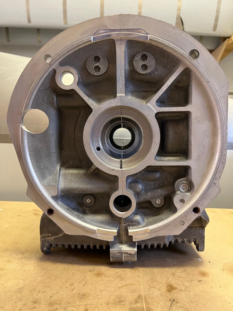
I started the crank case preparation shortly after receiving the engine kit back in August. I inspected the interior of the case for any remaining machining chips. I blew the case out with compressed air and spent time using a deburring tool to clean up any edges or holes that appeared to have burrs. I also looked at the cast in drain passages at each end of the for both the crank and the cam shaft to be sure they were clear to allow oil to return. After this, I washed the case in soap and water, blew it dry and set it in the sun for a final drying.
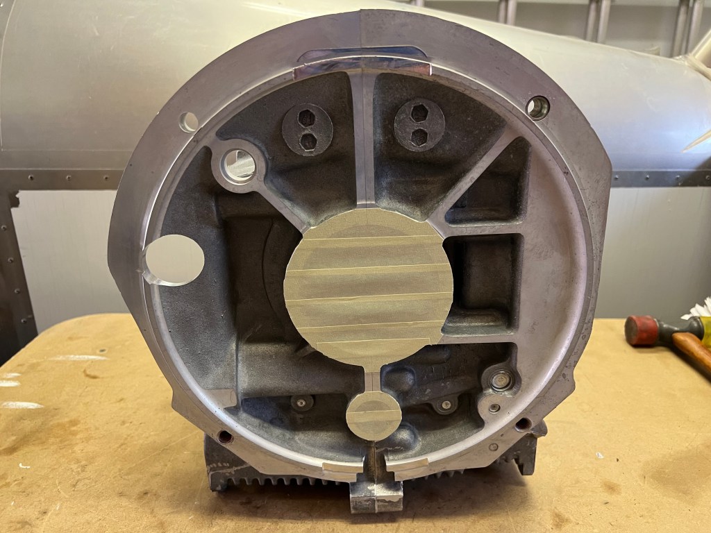
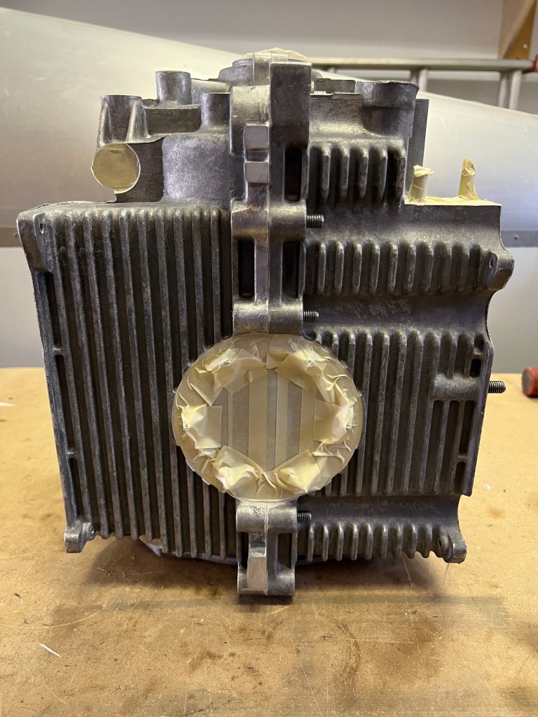
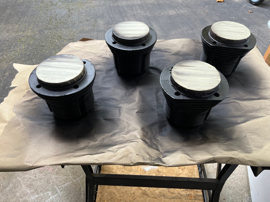
Next, I mated the two case halves and proceeded to mask up all of the openings so that I could paint the outside of the case. I also decided to paint the cylinders at the same time.


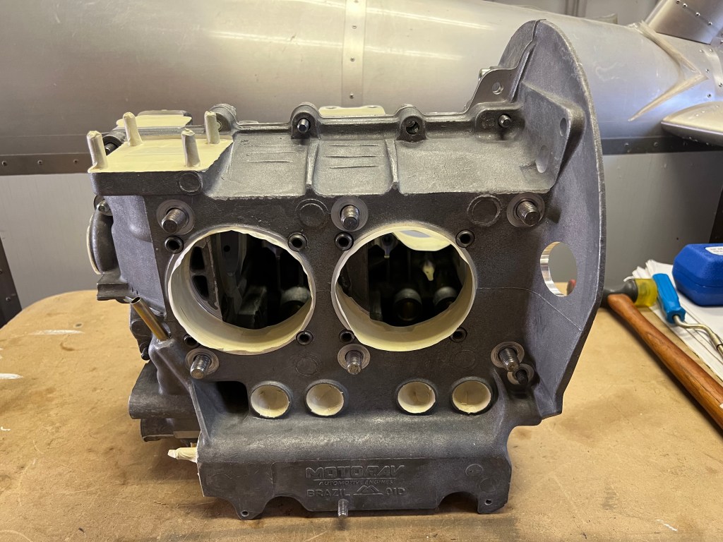


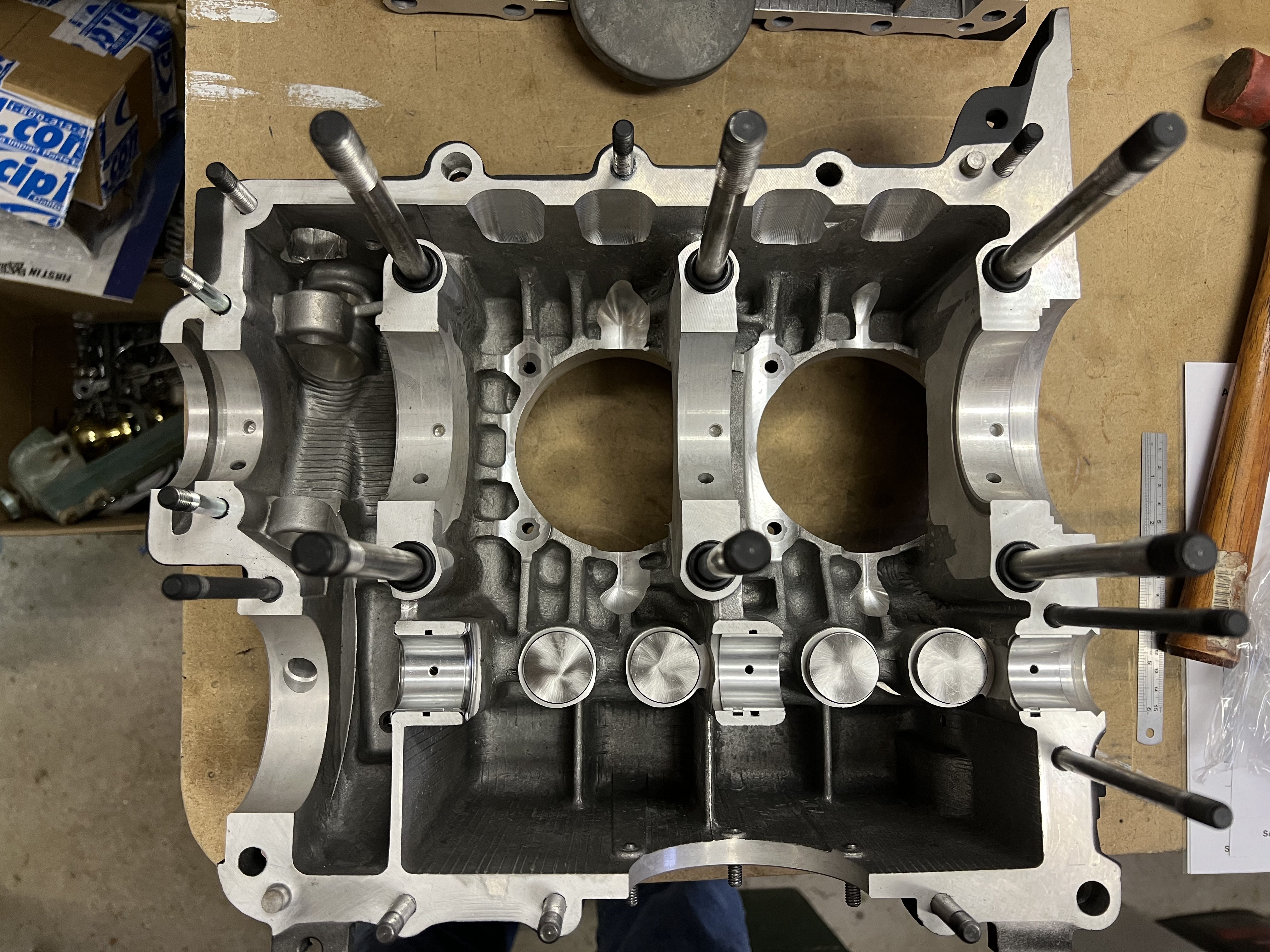
I decided to leave the installation of the head studs until after the case was joined or at least until I had an engine stand to put the case on. This seemed to make it easier to prepare the case for assembly as the two halves would lay on the work bench easier without the studs.
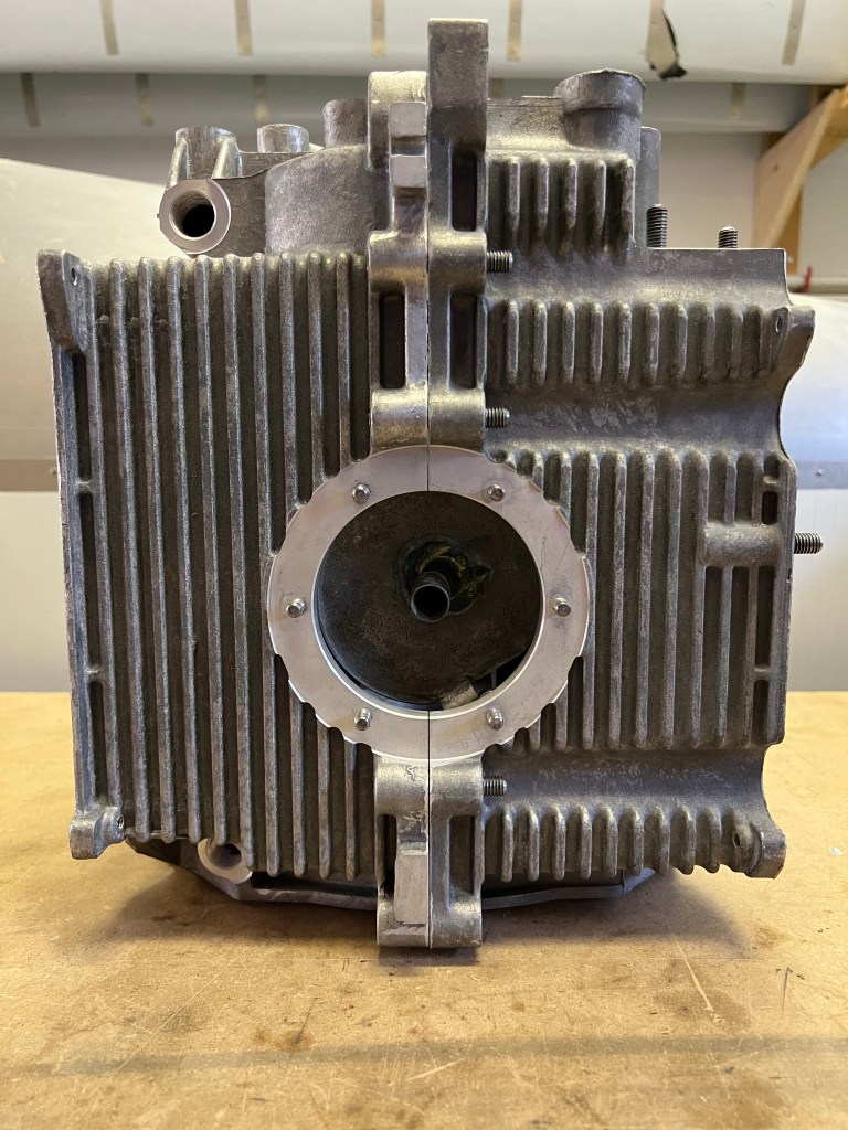
The next step was to install the oil pressure relief valve and the oil control valve. These were lubricated with oil and installed according to the manual. There is no torque spec for the plugs. The original VW plugs have slotted heads are are not intended to be tightened more than is required to compress the gasket. The plugs in the kit have a 17mm head. I used a 17mm wrench and made sure that the plugs were tight but only used moderate pressure to ensure I didn’t over tighten them in the case.


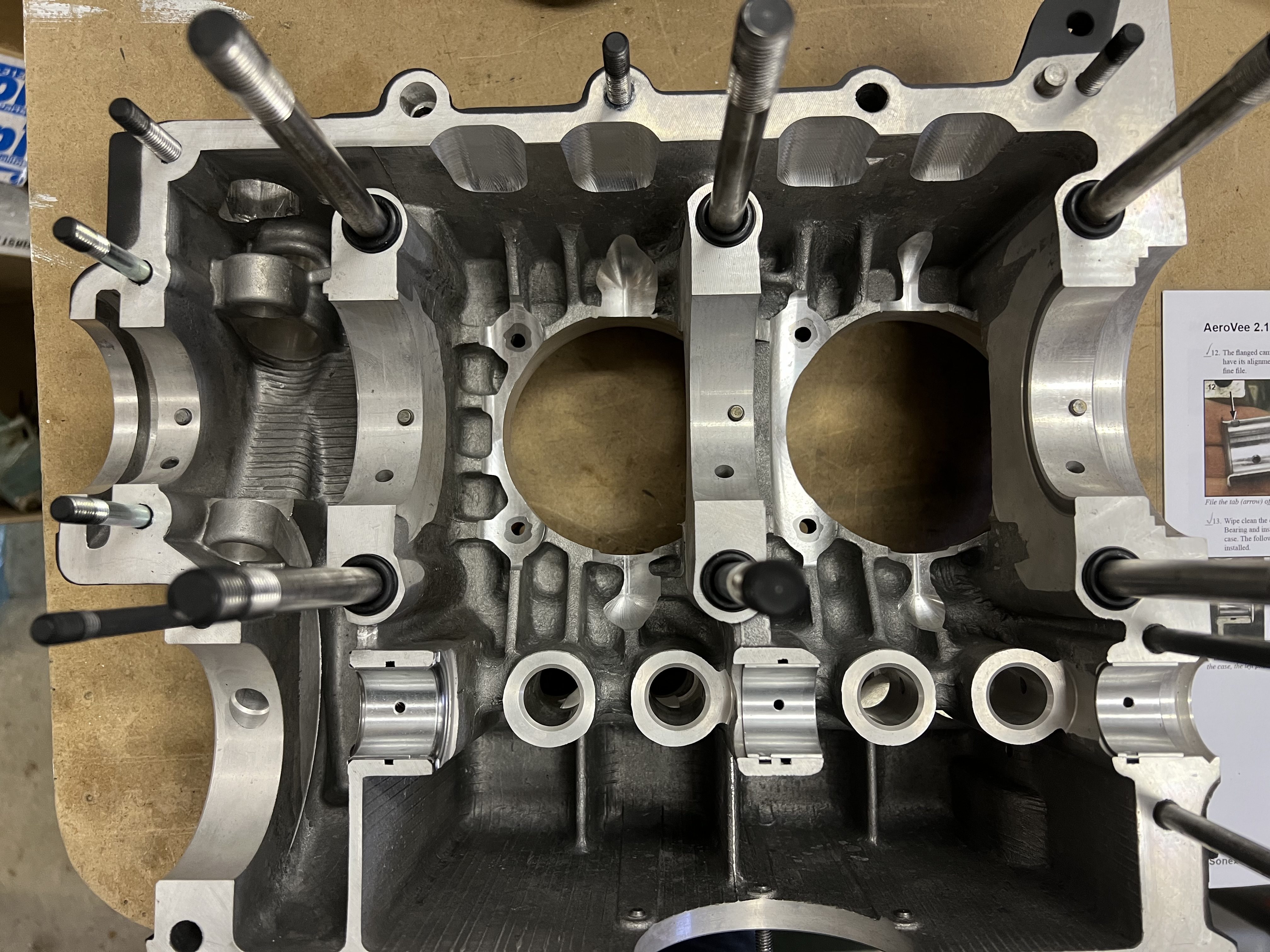
I installed the main bearing stud seals and proceeded to work on the cam bearings. I wiped the cam journals and installed the bearings in the left half of the case. I inadvertently installed the wrong bearing in the front (prop) end of the engine. This was noticeable because the longer bearing covers most of the oil return passage. Once I noticed this I swapped the two bearings. For the right half of the case, the flanged bearing must have its anti-rotation tab filed off. I filled this off with a small flat file and fit the cam bearings to the right hand side.
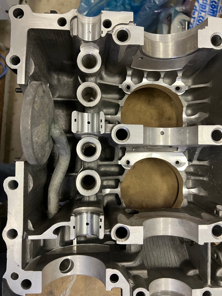


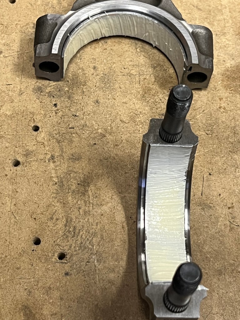
The final steps in the preparation were to test fit the lifters to be sure they didn’t bind and to verify the cam did not interfere with the lifters. Then the dowel pins were installed in the various main journals to anchor the main bearings and the two half journal bearings were installed. Fitting the dowel pins was a bit of a challenge. If you don’t get them started just right they will not go in. It took me a bit to get two of them to fit correctly.


You must be logged in to post a comment.