Last weekend, I installed the oil pump. I have a top-mounted oil cooler, so the pump is a straight pump, not the maxi oil pump. The installation manual mentions using form-a-gasket #3 or flange sealant. The Sonex assembly video mentions using Fuellube, available from Aircraft Spruce. I ordered some of this for assembly. The Fuellube is exceptionally sticky. I was worried I might tear the gaskets when applying it. Again, this was a relatively simple assembly effort.
One thing that I struggled with was finding the correct bolts. The manual does not mention the bolt part numbers. The bolts are the same thread size as the intake manifold bolts, and I double-checked the length to be sure they would not bottom out before completing the assembly. It seems there were two sets of these bolts in the kit. I will follow up on these bolts before I finish the engine.
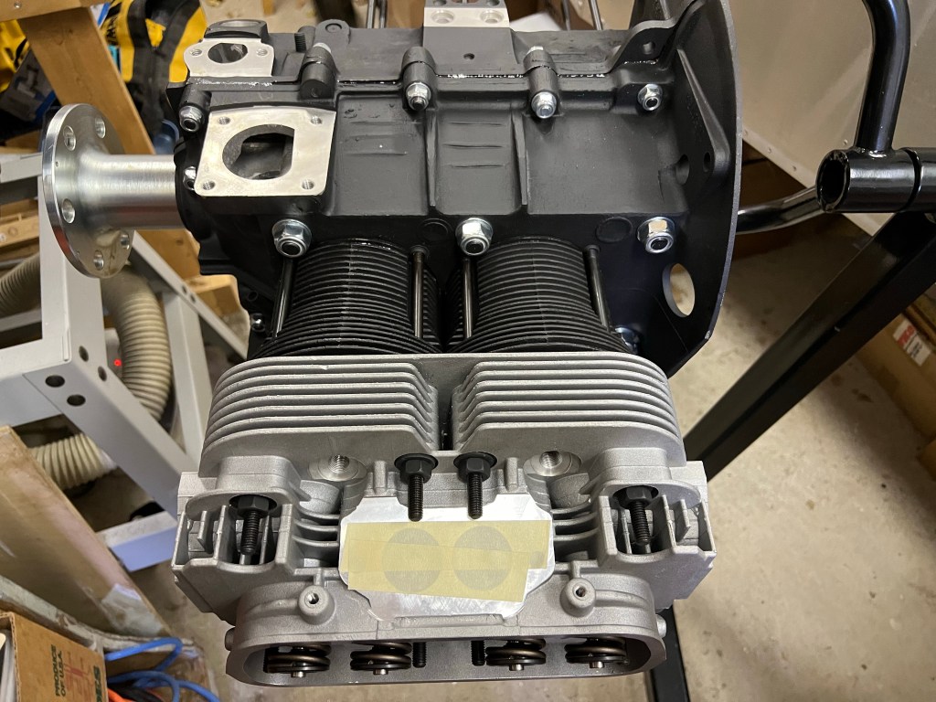
I worked on installing the cylinders, pistons and cylinder heads on one side of the engine today. My goal was to complete one side before starting the other. The reason for working on one side at a time was to try and ensure a good seal for the cylinders. I figured that if the cylinders were installed, but the cylinder heads were not, there would be no pressure to help seal the cylinders and allow the Permatex Aviation Form-A-Gasket #3 to seal properly. I’m not sure if this is entirely true. It claims to be non-hardening and slow-drying.
I started by reviewing the cylinder spacer selection based on wanting to run 8.0: 1 compression for aviation fuel. I used some mineral spirits to clean up excess oil from the mating surface of the cylinders and the spacers. Next, I checked the piston orientation in each of the two cylinders I was going to start with to be sure the arrows would be pointing to the flywheel. I pulled the pistons out the bottom of the cylinders enough to allow the wrist pins to slide out. I put the snap rings in one side of each piston so that I could install the pistons and still be able to put the snap rings in from the front and back of the pistons after sliding the wrist pins in.
Orienting the wrist pins required some though. For the first piston, it does not matter which direction the wrist pin slides in from. But when you install the second piston you have have the wrist pin slide in from the outside, away from the first cylinder.
After installing the cylinders and spacers, I installed the cylinder head with the head gaskets and push rod tubes. Next, I measured and started trimming the cylinder studs. I needed to cut down 5 of these to ensure clearance from the rockers and the intake manifold. For each of these, I used some form a gasket on the threads to the crank case as I reinstalled the studs. I plan to do the same for the remaining studs after re-installing the studs that I cut down
I started today by getting out the cylinders heads. I want to have them ready to install right after I install the cylinders. Why? The cylinders are installed using Permatex Aviation Form-A-Gasket #3 and I would like to install the cylinder heads and have them secured while the Permatex cures. Since I only work on the engine in frequently I did not want to install the cylinders and then leave them to sit for a few days or weeks until I got to the cylinder heads.
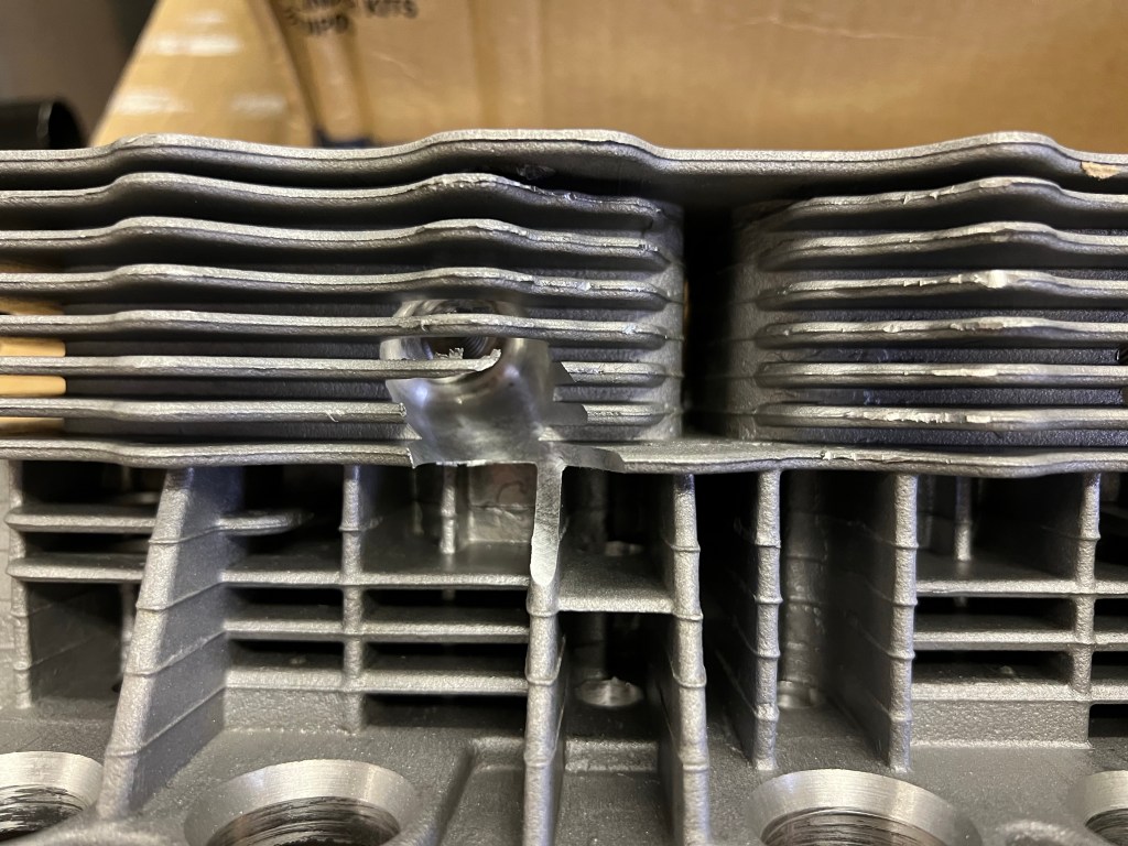
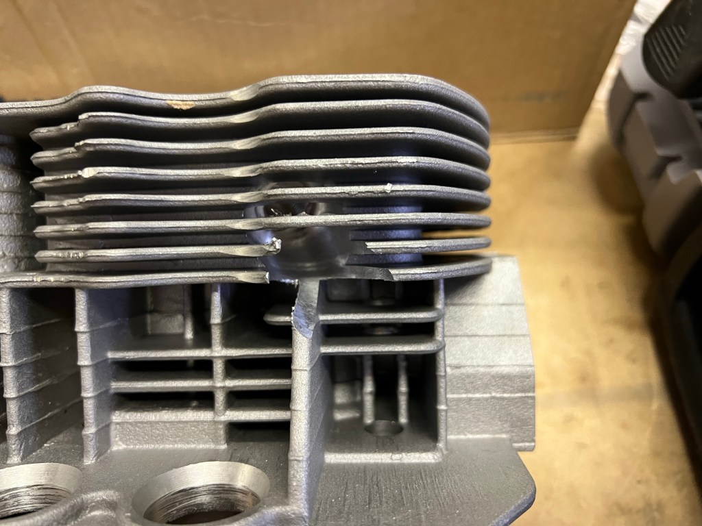
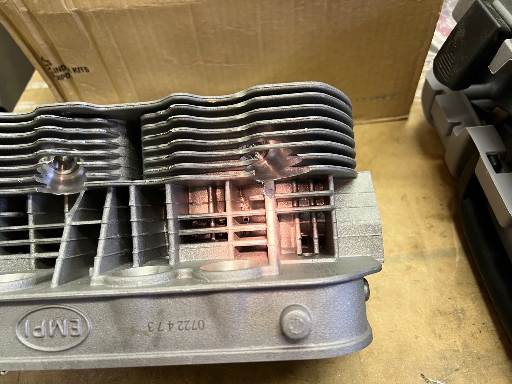
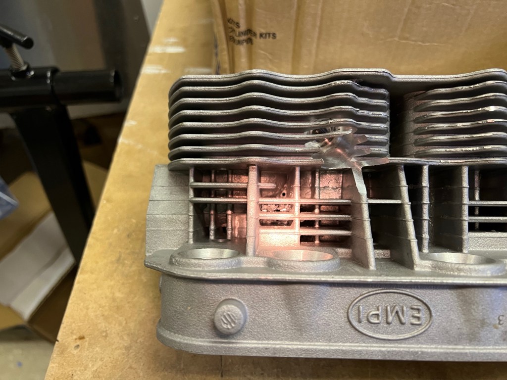
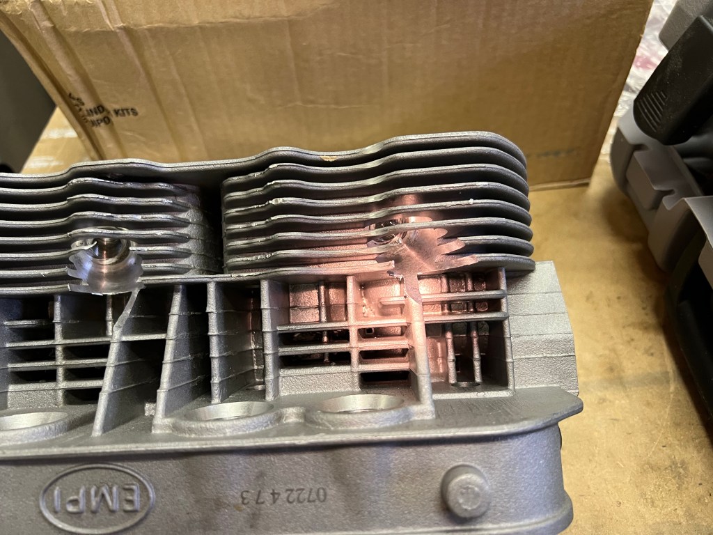
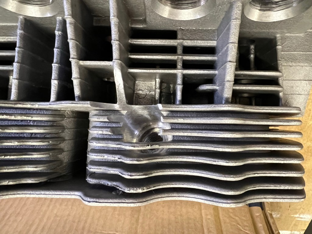
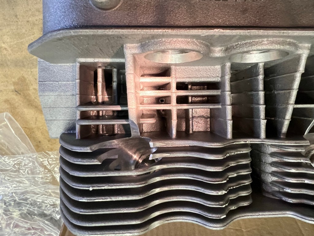
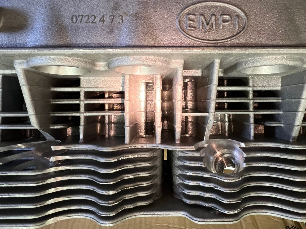
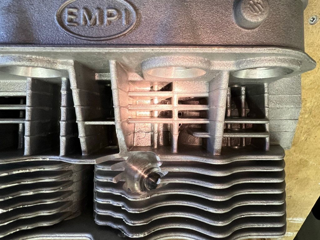
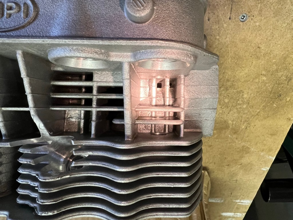
The instruction to clean the heads of machining debris is shown in bold text and identified as Important right after the parts required list. Hopefully, nobody skips ahead to the first step without doing the required cleaning. I found alot of debris in my heads.
Some of the Debris found in my Cylinder Heads
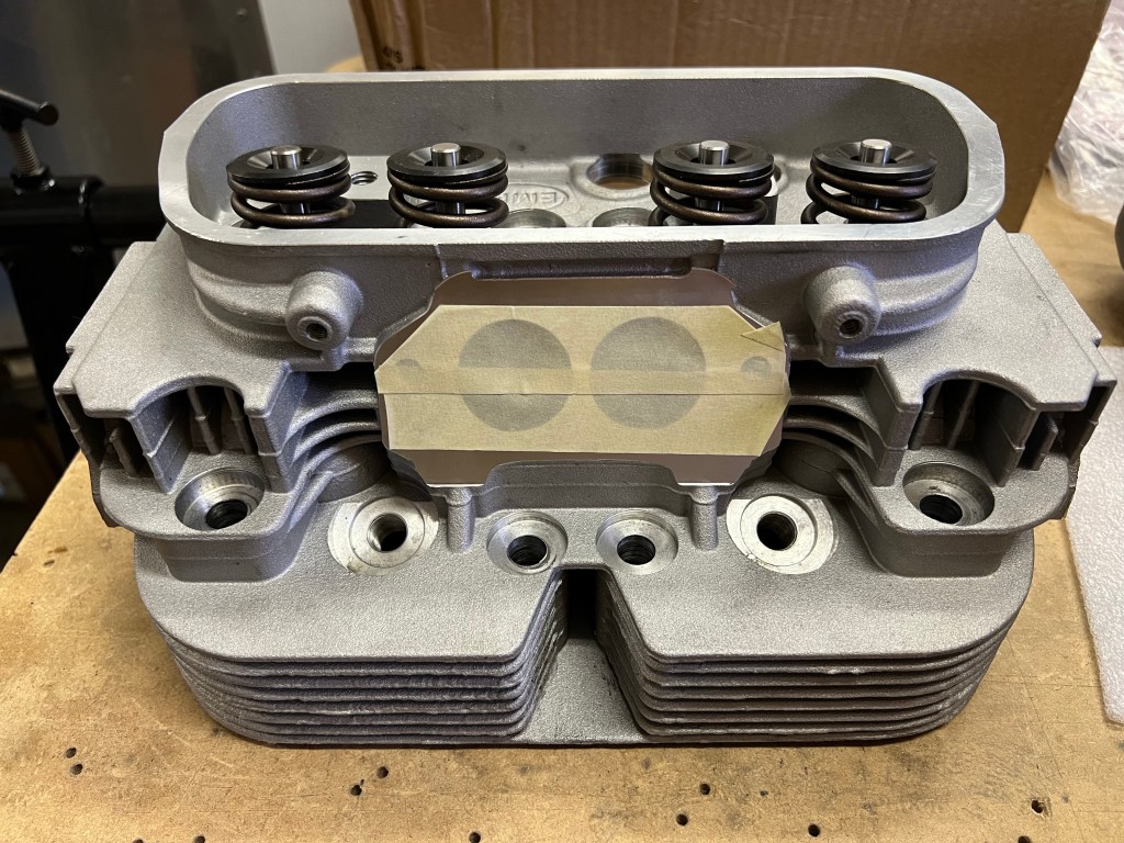
Before I started working on the chips I used masking tape to close up the intake and exhaust ports. I still planned to blow these out later but I figured it was better to keep the chips out of there right from the start.
Ports Taped Closed
I used a small scrapper and a deburring tool to remove the worst of the aluminum chips. I also used a piece of bare 14 gauge copper wire to get to the bottom of some of the tight areas to get the chips out. In the areas where the secondary spark plug holes were added, I cleaned up the sharp areas with a Dremel tool and then some scotch bright pads to break the sharp edges. I used compressed air on several occasions to blow out the chips.


You must be logged in to post a comment.