Installing Cylinders and Heads

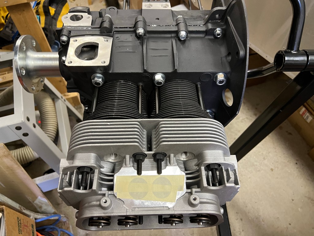
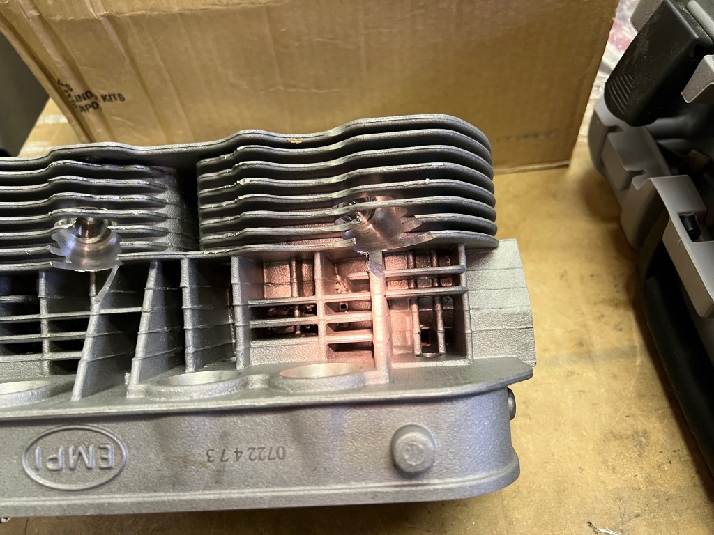
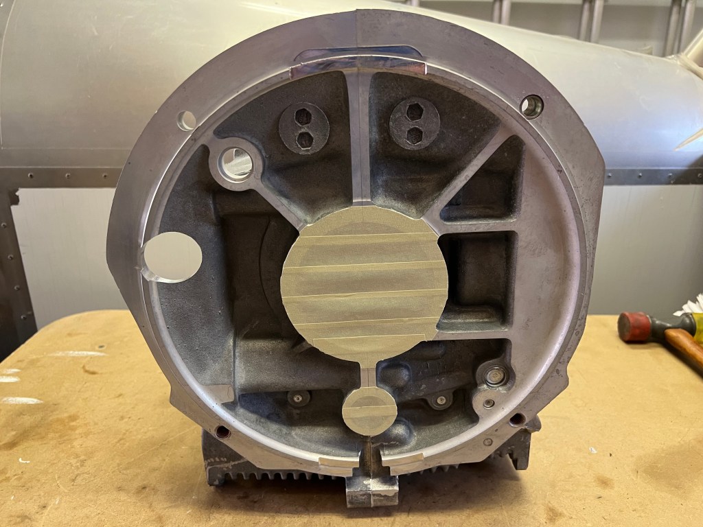
I worked on installing the cylinders, pistons and cylinder heads on one side of the engine today. My goal was to complete one side before starting the other. The reason for working on one side at a time was to try and ensure a good seal for the cylinders. I figured that if the cylinders were installed, but the cylinder heads were not, there would be no pressure to help seal the cylinders and allow the Permatex Aviation Form-A-Gasket to seal properly. I’m not sure if this is entirely true. It claims to be non-hardening and slow-drying.

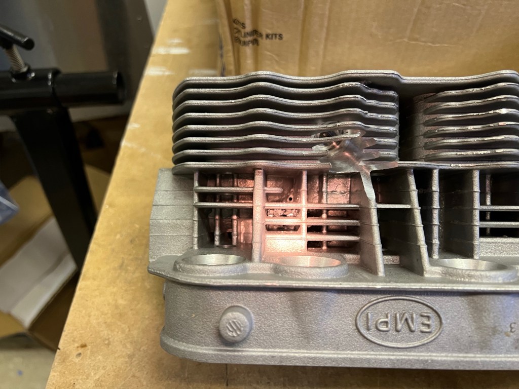
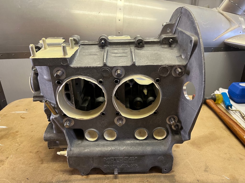
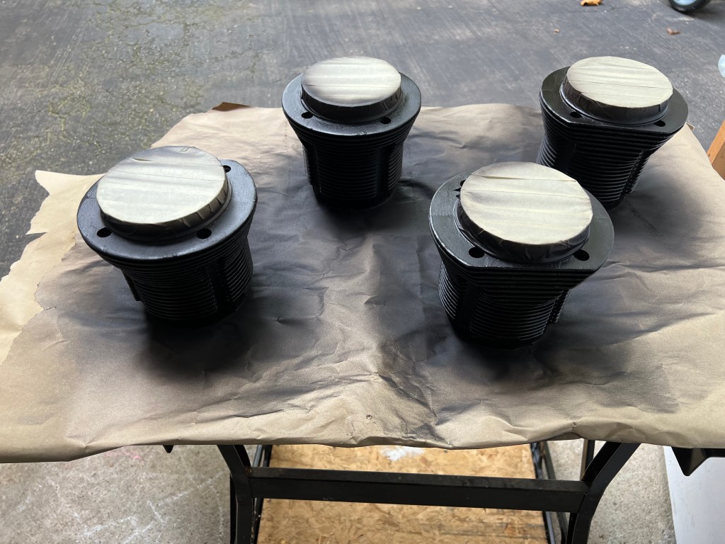
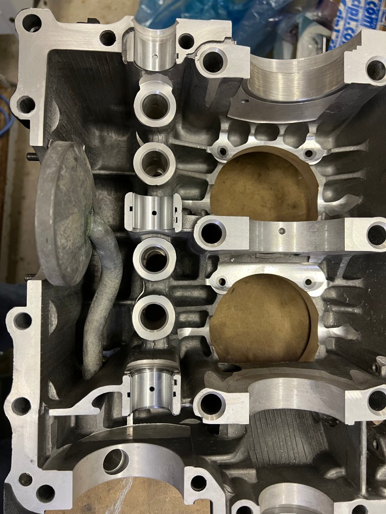
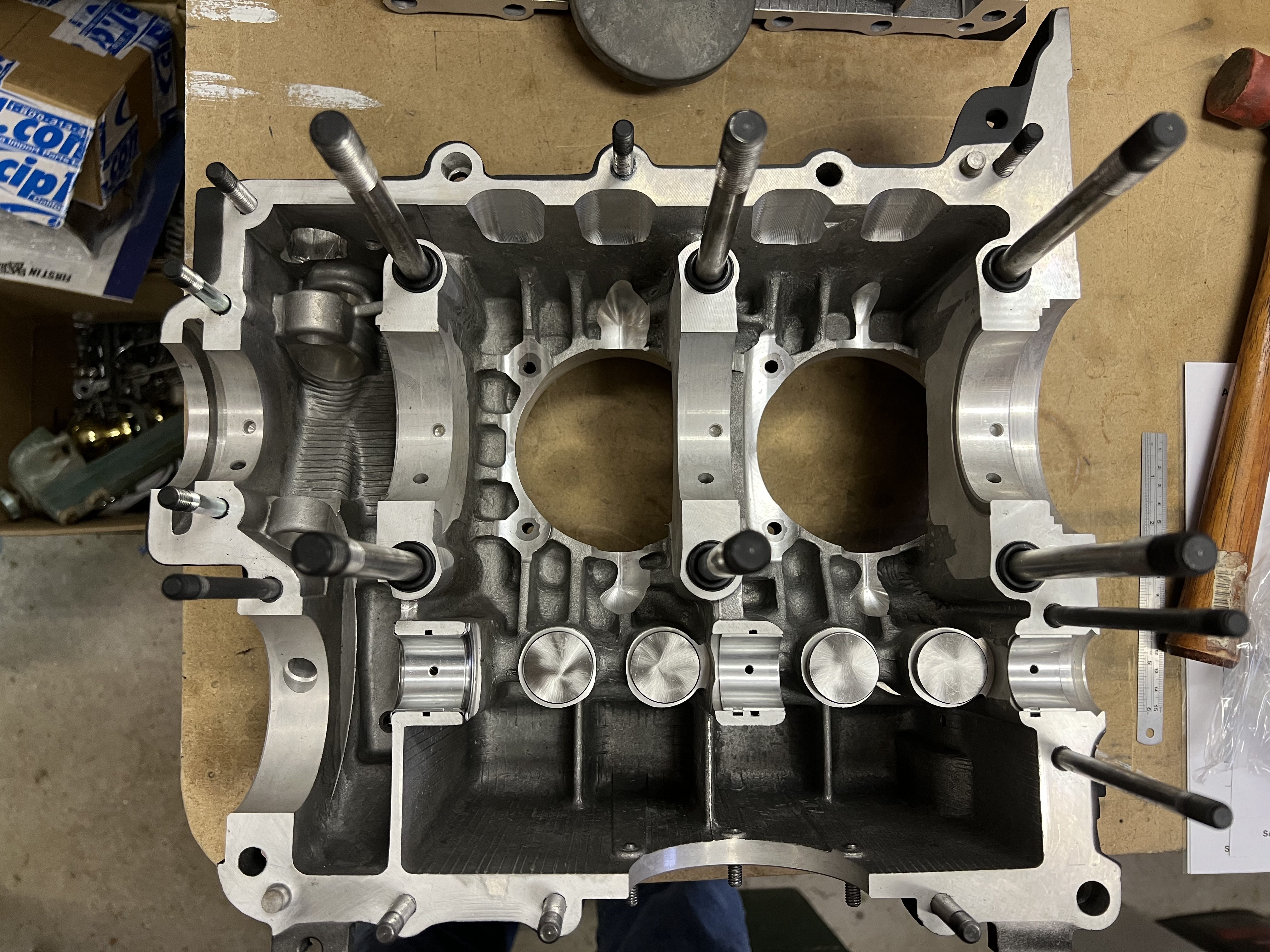
I started by reviewing the cylinder spacer selection based on wanting to run 8.0: 1 compression for aviation fuel. I used some mineral spirits to clean up excess oil from the mating surface of the cylinders and the spacers. Next, I checked the piston orientation in each of the two cylinders I was going to start with to be sure the arrows would be pointing to the flywheel. I pulled the pistons out the bottom of the cylinders enough to allow the wrist pins to slide out. I put the snap rings in one side of each piston so that I could install the pistons and still be able to put the snap rings in from the front and back of the pistons after sliding the wrist pins in.

Orienting the wrist pins required some though. For the first piston, it does not matter which direction the wrist pin slides in from. But when you install the second piston you have have the wrist pin slide in from the outside, away from the first cylinder.

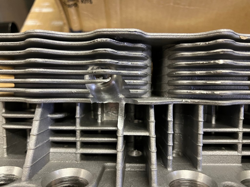
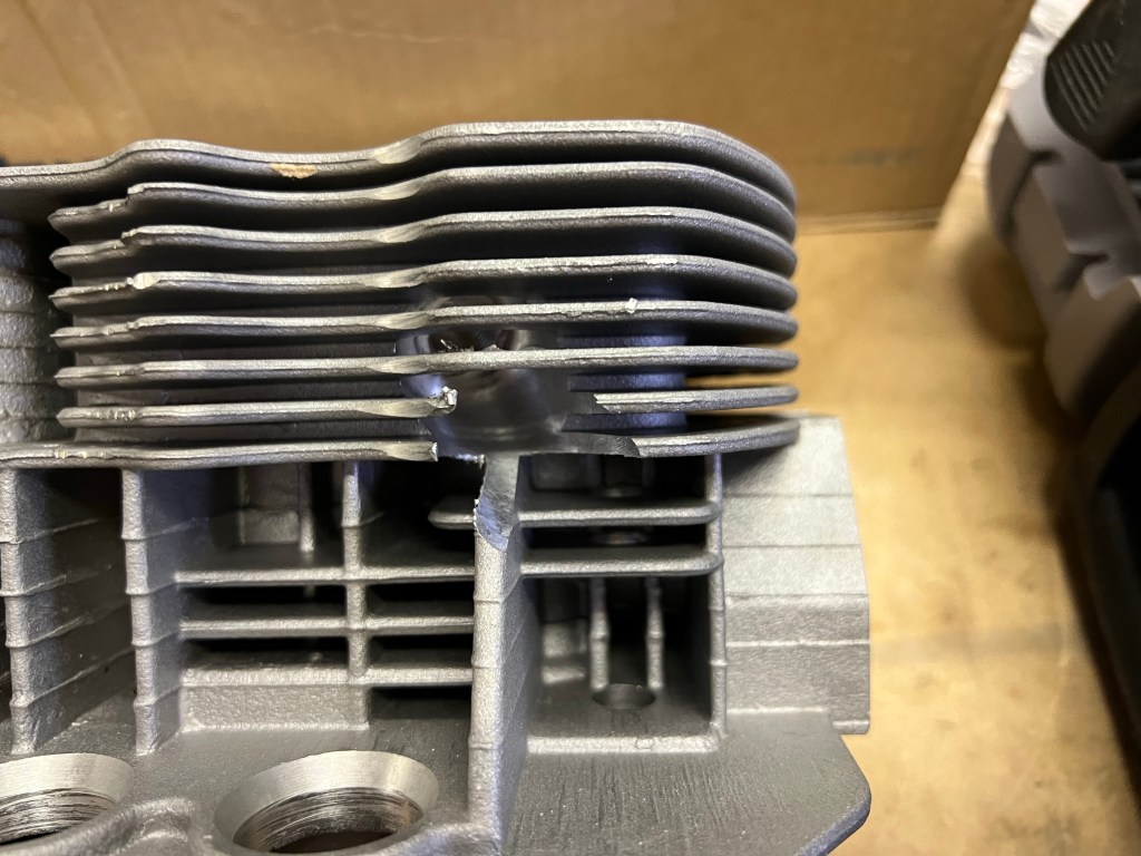
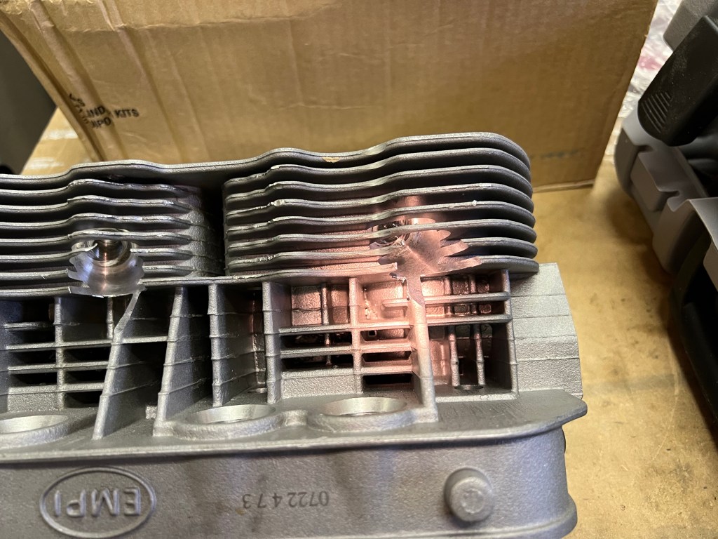
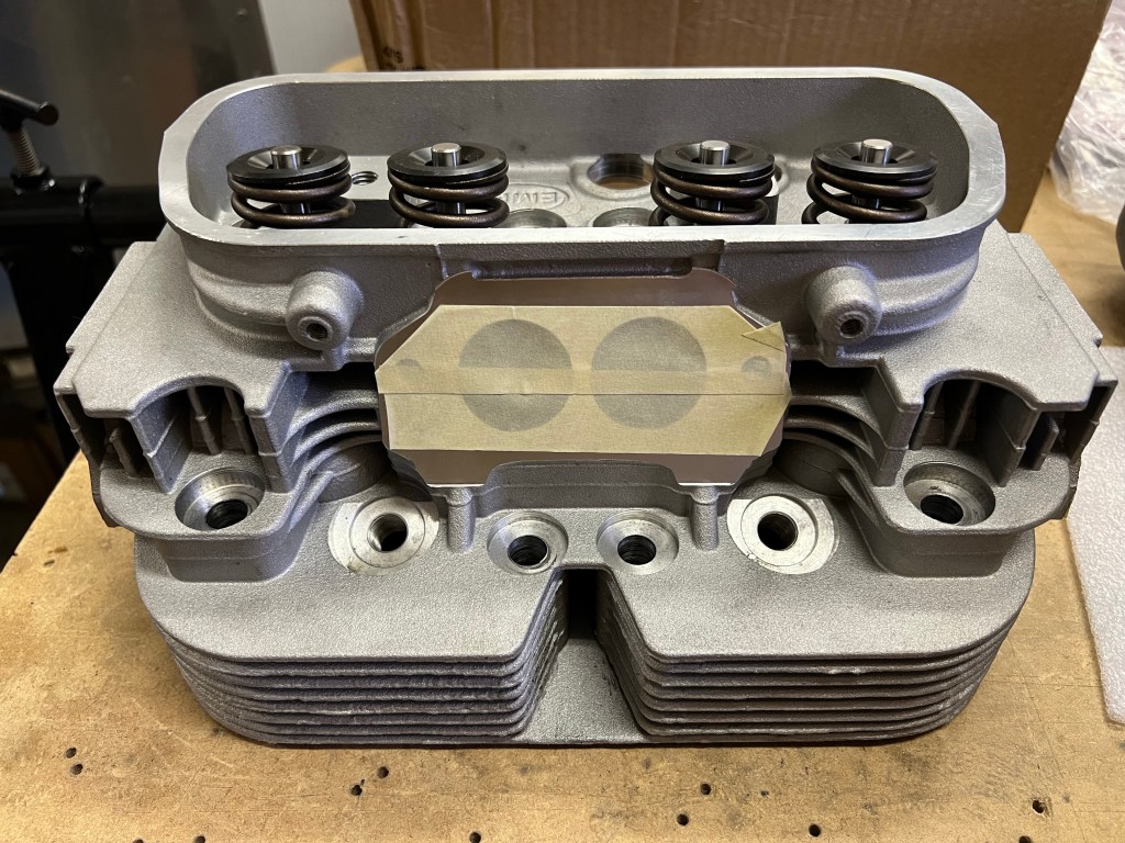
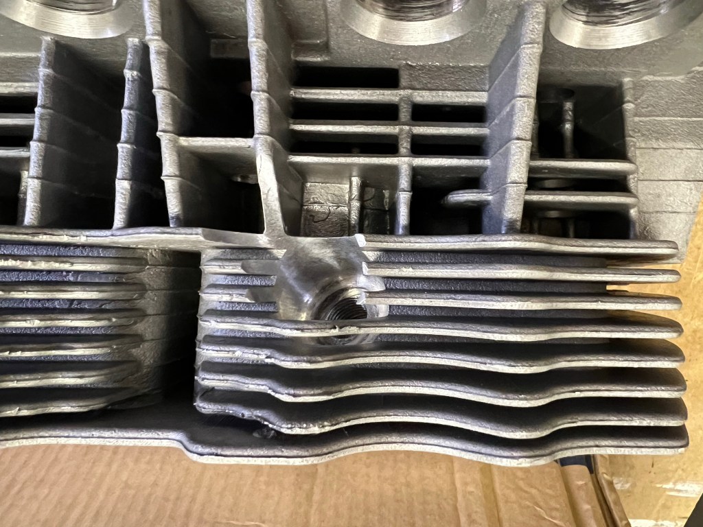
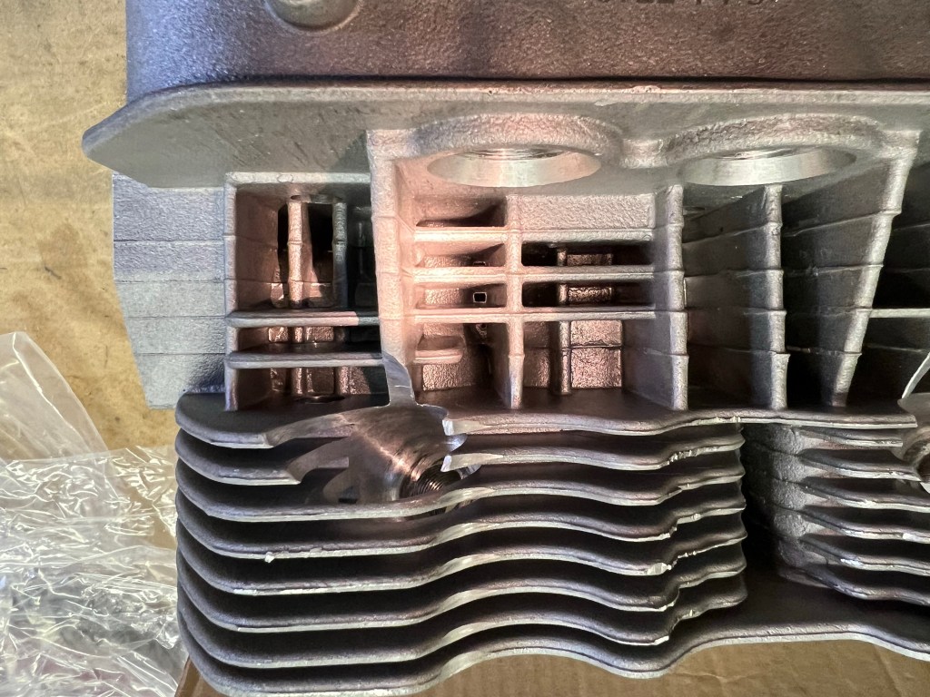
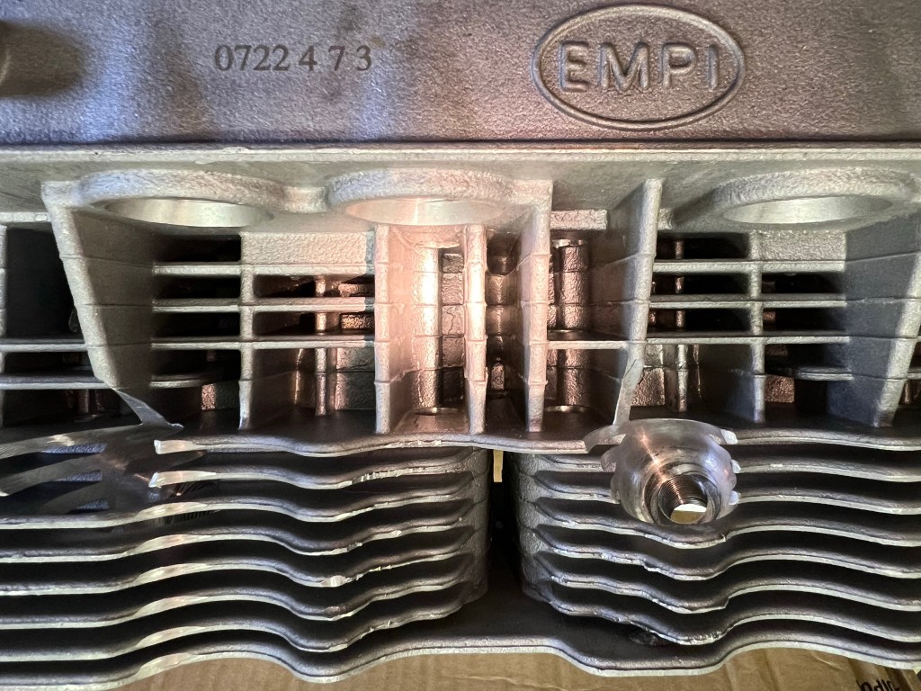
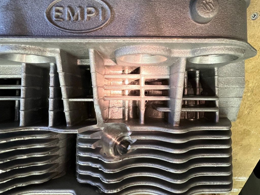
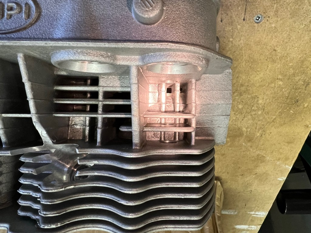
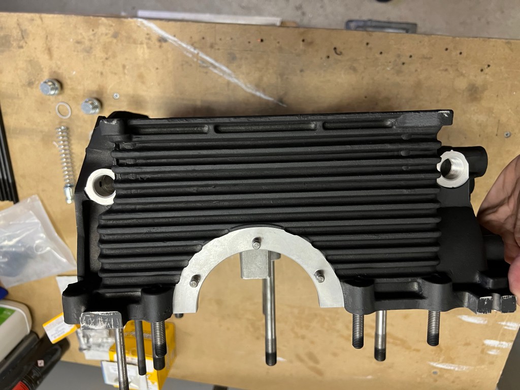
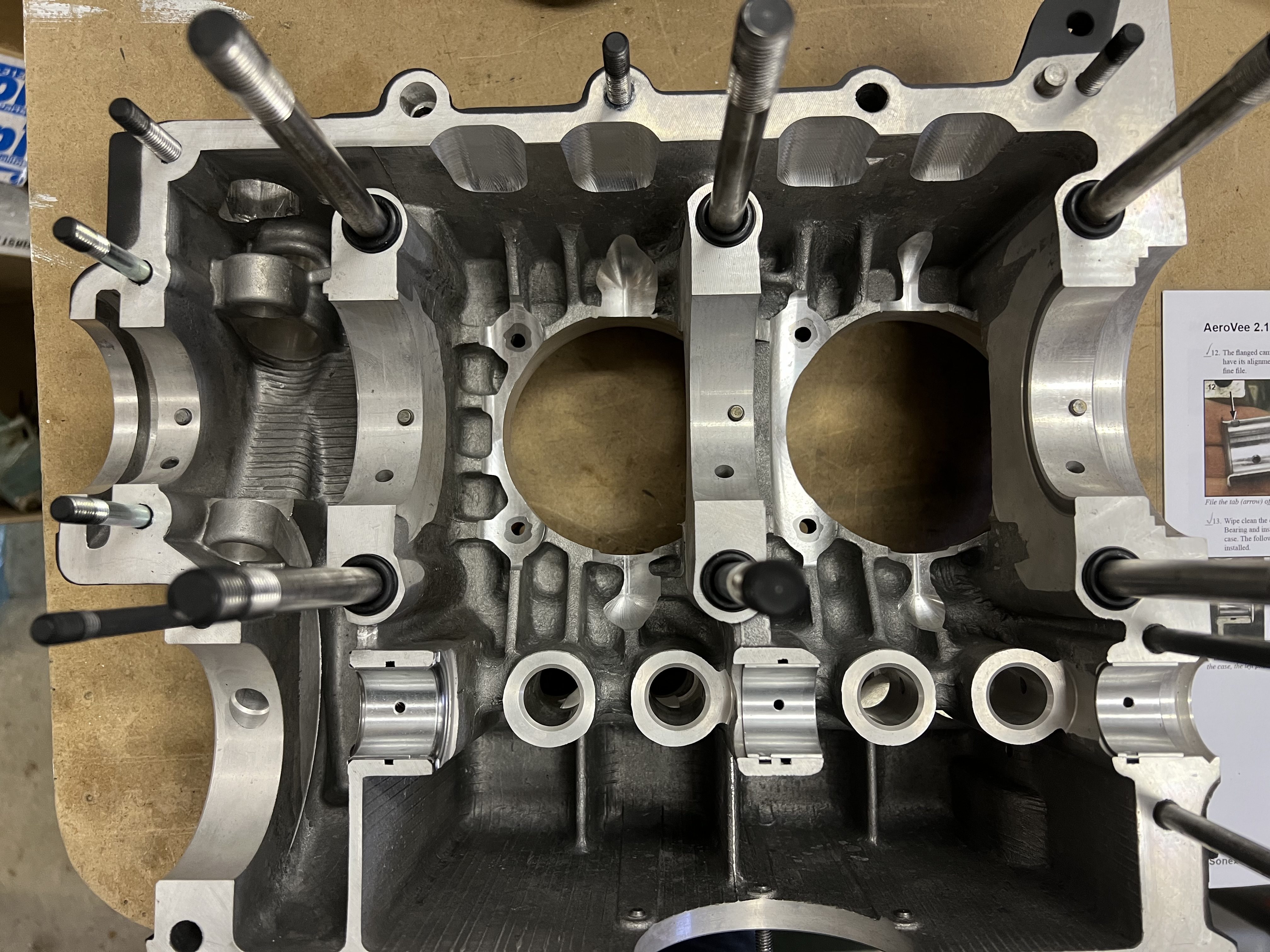
After installing the cylinders and spacers, I installed the cylinder head with the head gaskets and push rod tubes. Next, I measured and started trimming the cylinder studs. I needed to cut down 5 of these to ensure clearance from the rockers and the intake manifold. For each of these, I used some form a gasket on the threads to the crank case as I reinstalled the studs. I plan to do the same for the remaining studs after re-installing the studs that I cut down

Cylinder Head Installed – Before Trimming Studs.

Cleaning Cylinder Heads

I started today by getting out the cylinders heads. I want to have them ready to install right after I install the cylinders. Why? The cylinders are installed using Permatex Aviation Form-A-Gasket and I would like to install the cylinder heads and have them secured while the Permatex cures. Since I only work on the engine in frequently I did not want to install the cylinders and then leave them to sit for a few days or weeks until I got to the cylinder heads.

The instruction to clean the heads of machining debris is shown in bold text and identified as Important right after the parts required list. Hopefully, nobody skips ahead to the first step without doing the required cleaning. I found alot of debris in my heads.

Before I started working on the chips I used masking tape to close up the intake and exhaust ports. I still planned to blow these out later but I figured it was better to keep the chips out of there right from the start.

I used a small scrapper and a deburring tool to remove the worst of the aluminum chips. I also used a piece of bare 14 gauge copper wire to get to the bottom of some of the tight areas to get the chips out. In the areas where the secondary spark plug holes were added, I cleaned up the sharp areas with a Dremel tool and then some scotch bright pads to break the sharp edges. I used compressed air on several occasions to blow out the chips.

Crank Case Preparation

I started the crank case preparation shortly after receiving the engine kit back in August. I inspected the interior of the case for any remaining machining chips. I blew the case out with compressed air and spent time using a deburring tool to clean up any edges or holes that appeared to have burrs. I also looked at the cast in drain passages at each end of the for both the crank and the cam shaft to be sure they were clear to allow oil to return. After this, I washed the case in soap and water, blew it dry and set it in the sun for a final drying.

Next, I mated the two case halves and proceeded to mask up all of the openings so that I could paint the outside of the case. I also decided to paint the cylinders at the same time.

I decided to leave the installation of the head studs until after the case was joined or at least until I had an engine stand to put the case on. This seemed to make it easier to prepare the case for assembly as the two halves would lay on the work bench easier without the studs.

The next step was to install the oil pressure relief valve and the oil control valve. These were lubricated with oil and installed according to the manual. There is no torque spec for the plugs. The original VW plugs have slotted heads are are not intended to be tightened more than is required to compress the gasket. The plugs in the kit have a 17mm head. I used a 17mm wrench and made sure that the plugs were tight but only used moderate pressure to ensure I didn’t over tighten them in the case.

I installed the main bearing stud seals and proceeded to work on the cam bearings. I wiped the cam journals and installed the bearings in the left half of the case. I inadvertently installed the wrong bearing in the front (prop) end of the engine. This was noticeable because the longer bearing covers most of the oil return passage. Once I noticed this I swapped the two bearings. For the right half of the case, the flanged bearing must have its anti-rotation tab filed off. I filled this off with a small flat file and fit the cam bearings to the right hand side.

The final steps in the preparation were to test fit the lifters to be sure they didn’t bind and to verify the cam did not interfere with the lifters. Then the dowel pins were installed in the various main journals to anchor the main bearings and the two half journal bearings were installed. Fitting the dowel pins was a bit of a challenge. If you don’t get them started just right they will not go in. It took me a bit to get two of them to fit correctly.

Preparing Engine Block For Paint

I continued preparing the engine block for paint today. I deburred a couple of remaining threaded holes and applied masking tape to the various surfaces that need to be kept free of paint. The Aeroconversion AeroVee assembly video helped me identify which of the various surfaces needed to be protected. For the cylinder openings in the block I used the lids from various coffee cans to close in the openings.

Front View (AeroVee) with most openings taped up.
Side view with cylinders still open.

After getting the engine fully masked I put it on a bench outside and proceeded to apply the paint. I let it dry and then a few days later removed the masking.