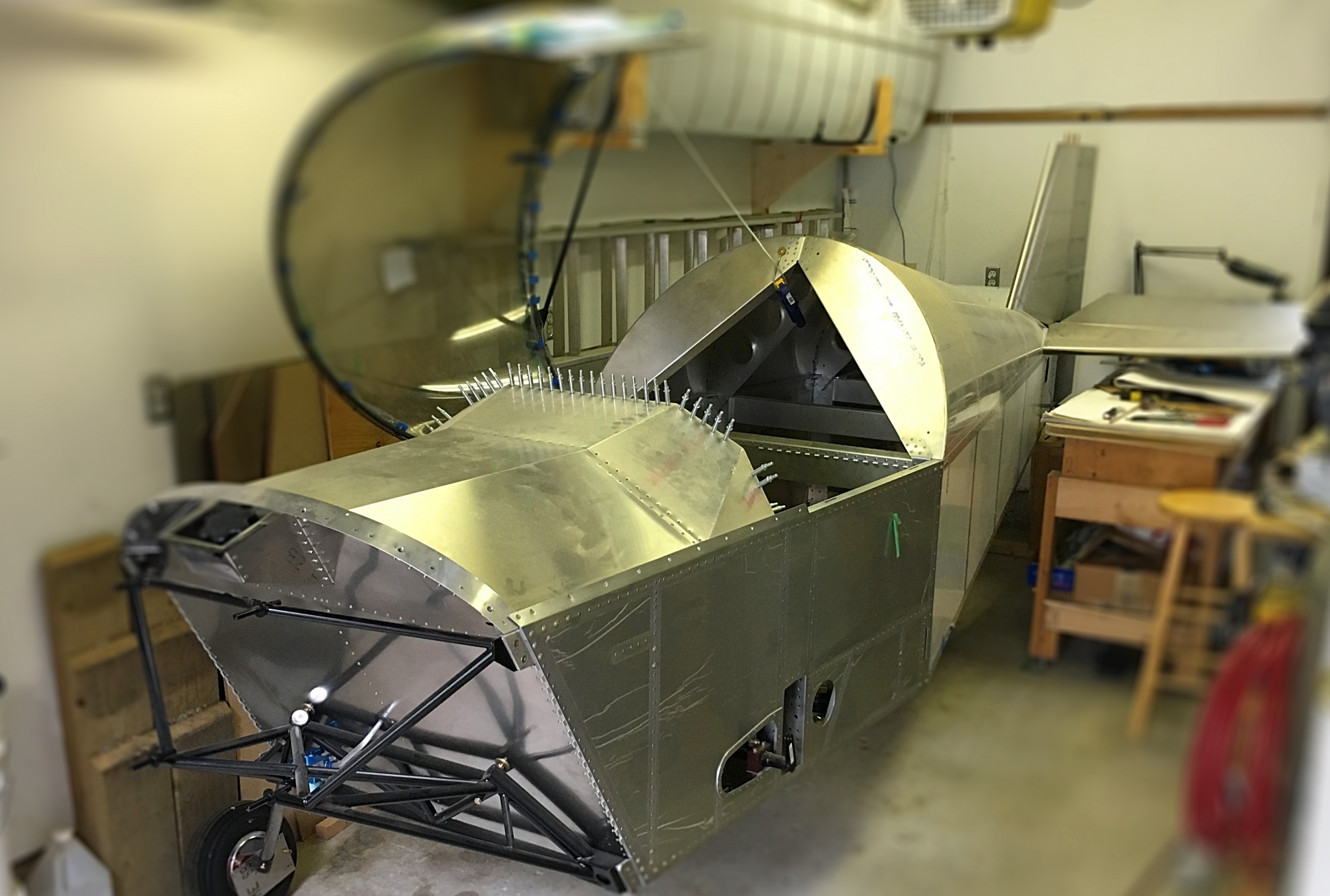
I have been working on the rocker shaft installation for a week or two now. Based on everything I’ve learned, I suggest following the AeroVee manual. It just works.
Being a mechanical engineer, I put too much thought into this process and concluded that what is presented in the manual is correct, even if it seems very simplified. When I started, I wondered about the placement of the swivel pad on the valve stem. My initial thought was that due to the angular or rotational motion of the rocker arms, the pad would slide back and forth on the top of the valve stem. While this is correct, I also thought that they should slide back and forth across the centre of the valve stem in an ideal setup. This part I am not so sure about.
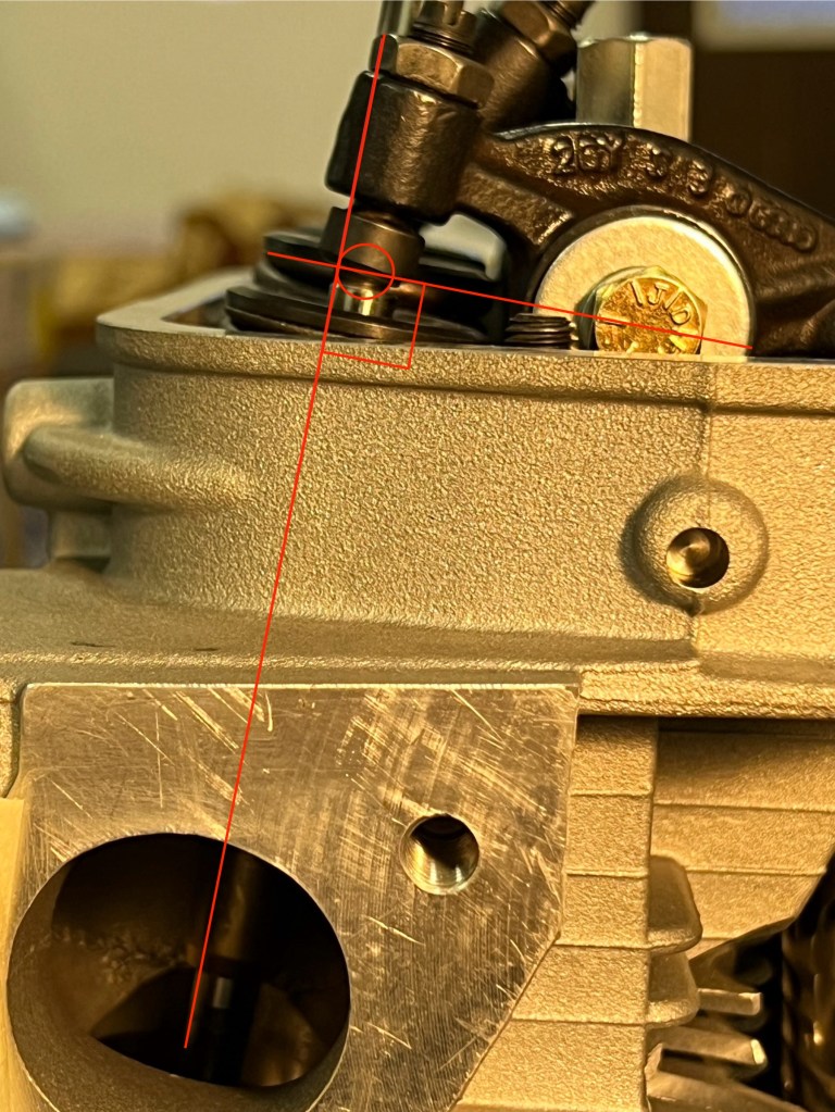
I read a lot of forum posts about VW type 1 engine valve geometry, and many talk about the setup at 1/2 lift. The idea is that you want the correct geometry at 1/2 valve actuation. What I mean by correct geometry is that you are looking to have the line from the centre of the rocker shaft to the point of contact (or point of no moment, more on this later) being perpendicular to the valve stem. This made sense to me as you will apply some side loads to the valve stem on either side of this position as the rocker arm moves through an arc.
To change the geometry, you can either make changes at the adjuster or you can shim the rocker arm shaft. The AeroVee manual and many websites suggest setting the adjuster to between 1 and 2 turns out from the swivel pad being against the rocker. (The AreoVee manual says 1-1/2) turns. With this setup, you can only add or remove shims under the rocker shaft to change the geometry.
The mounting studs for the rocker shaft are not parallel to the valve stems. This means that as you add shims under the rocker shaft, you are both moving it upwards in the direction of the end of the valve stem and, at the same time, moving it closer to the valve stem. This changes the angle of contact at 1/2 lift and the position of contact on the end of the valve stem. Adding shims generally moves the position of contact away from the rocker shaft while removing shims does the opposite.
The AeroVee manual wants the rocker shaft shimmed so that the point of contact is not in the centre of the valve stem but past the centre of the valve stem away from the centre of the rocker shaft when the valve is fully closed. This did not make sense to me because as the rocker arm rotates, it will move further away from the rocker shaft until it reaches a point where the radius is 90 degrees to the rocker shaft and then the position of contact will move back towards the rocker shaft for the remainder of its movement. I thought it would make sense to have the starting point closer to the rocker shaft, then as the rocker arm rotates, the position of contact would move through the centre of the valve to a point on the opposite side of the centre at 1/2 lift and then would return back to its starting point at full lift.
Another consideration is trying to get the maximum lift of the valves available from the cam. Depending on the geometry at both the push rod end of the rocker and the valve end of the rocker, you will get different amounts of lift. I’m unsure what the actual lift for the AeroVee should be, as I didn’t check out the cam information when I unpacked it.
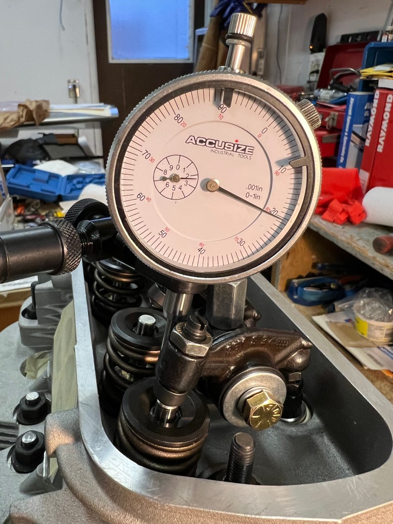
I purchased a dial indicator and mount during this exercise to find the 1/2 lift point and examine the geometry. During my various measurements, I got a maximum valve lift of 0.440″ measure at the top of the valve.

While reading the various forum posts, I came across one suggesting that the point of contact between the rock and valve with a swivel pad adjuster is actually the centre of the adjuster ball. This actually makes sense as the point of contact is where no moment is transmitted, and this will occur at the center of the ball.
With all of this in mind, I experimented with different numbers of shims under the rocker shaft. What I found was that with one 0.030″ shim, I was able to get the most valve lift and, at the same time, very close to the magic 90 degrees between the line from the rocker arm pivot to the center of the swivel ball and, the valve stem at 1/2 lift.
I noticed that the swivel pad’s movement across the tip of the valve is very small. I also found that with one shim in place, the position of contact was just past the centre of the valve, away from the rocker shaft, as described in the AeroVee Manual. At this point, I decided that the manual was right and that it would have been better just to follow it as the setup described. With all the work I did measuring thing I was not able to get any better setup.
With all of this figured out, it’s now time to get back to the rocker shaft installation and the trimming of the pushrods.

You must be logged in to post a comment.