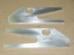
For the oval hole in the other attach plate I decided to drill a single hole and then cut the entire oval using a coping saw. This seemed to work quite well. I did some sanding with the drum sander. When I overlayed the parts I discovered that the two ovals were not the same size. After some measuring I discovered that I had measure one of the holes wrong. I was too small. Whew! Making a hole bigger is easier than making it smaller. After marking the correct hole size is used a round file to open up the hole.
Finishing The Attach Plates
I finished the attach plates today by drilling the 3/16 inch holes at the end of the plate and then sanding and scotch briteing the parts.
Drive Horn Template
The drive horn shown in the plans has no dimensions but is drawn full scale. I decided that the quickest way to make this part was to start with a template. I used a piece of drafting paper to trace the drive horn from the plans. I then glued the drafting paper to a piece of bristol board and cut it out. This provided a rigid template that I could trace for the final shape on the aluminum.<br /><br /> I traced the shape onto the aluminum and used the band saw to cut out the rough shape. Next, I started the sanding.
Holes In The Attach Plates
I started work on the large oval hole and the tail relief. On one of the attach plates I decided to drill a series of 3/32 inch holes around the perimeter of the large oval hole. Next, I used a coping (sp?) saw to cut between each of the holes and get a rough opening. Finally, I used a sanding drum in the drill press to start cleaning up the oval. I also used the band saw to cut the tail relief.
More Attach Plate Work
I finished sanding the large oval hole. Next I setup a fence on my drill press to allow me to drill all of the 3/32 inch pilot hole in a straight line. I clamped a piece of hardwood to the drill press table 1/4 of an inch from the centerline of the drill bit. This lets me drill exactly 1/4 inch from the edge of the part. All I have to do is line up each of the marks measured from the end of the attache plate.
Idler Plate
I drilled 3 pilot holes in the idler plate. All are 3/32" dia. I’m not exactly sure what size to drill the final holes. Two of the holes are called out at 1/4" and one is for an AN3 bolt. I haven’t figured out what goes in the 1/4" holes and I have found conflicting information on the AN3 bolt. Some literature says to drill it 3/16" and some info says I should drill it smaller so that I have a tighter fit on the bolt. I left the part with the pilot holes and will open them up later.
Spacer Block
I made the small spacer block. It was fairly straight forward. I used the bandsaw to cut the material and then files, sandpaper and scotch brite to finish it.
Left Hand and Right Hand Attach Plates
I started with one of my previously created strips of aluminum that is almost the correct width. I cleaned up the long edges using the vixen file, mill file, sandpaper and scotchbrite. The brought the strip to the correct width. Next I started laying out the part using an ultrafine sharpie right on the aluminum. I had to measure one of the angles at the nose of the part as it was not dimensioned on the prints.
More Work Today On the Attach Plates
Well, I got back at things again today. I find that an hour at a time is about right and gives me some thinking time. I finished marking out the attach plates and then cut them out on the band saw. I keep remembering to use a candle on the blade before any serious cutting and it sure keeps the blade clean. I used the bench sander after cutting to start cleaning up the edges.

Left and Right Hand Lower Horizontal Splice Plate
I formed the bend on these two parts. I noticed that the hardwood dowels I have been using were being crushed with use so I switched the one on the inside of the bend for a 1" OD socket. This seemed to work well. As usual I ended up with a bit of orange peel on the surface that disappeared with an application of scotch brite. I had a hard time guessing at the spring back and ended up over forming the parts a little. A few taps with a rubber mallet brought the bend back to the correct angle.

You must be logged in to post a comment.